Falconry Lure Machine

Thread Starter

Icarus1977

Joined Aug 4, 2014
91
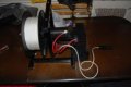
Now I see you what you mean... It's the same pulley I did the outside diameter of the pulley and tried to convert it to circumference, but failed miserably...
 

jpanhalt

Joined Jan 18, 2008
11,087
Basically I have built the test circuit as specified in the LM3524 guide (page 5), I have on pin 6 a 10K resistor and on pin 7 a 820pf capacitor this is giving me an output on pin 12 & 13 of 65.8KHz

but the output voltage is inverted as I have not yet used a 2k pull up resistor to Vin...

They use the formula fosc = 1 over RTCT
fosc = 1 over 10K x 820P
fosc = 1 over 0.0082
fosc = 121
According to your calculation, "fosc = 121" x ? (i.e., what's the exponent?)


10K = 10^4 Ω
820pF = 820X10^-12 F

10^4 X 820X10-12 = 820X10^-8 = 0.82X10^-5 seconds/cycle

1/(0.82X10-5) = 1.22X10^5 = 122 KHz

Why did you pick such a high frequency?

The datasheet recommends that the timing capacitor be at least 1000 pF, so for starters, your capacitor is too small.

If you use a 0.01 uF capacitor and a 10K resistor, you should get 10 KHz. That may still be higher than you want, but hopefully you see the pattern. There is also a table in the datasheet which can be used to select resistor and capacitor values.

How are you measuring the frequency?

John
 

Thread Starter

Icarus1977

Joined Aug 4, 2014
91
I have not picked a high frequency, just used a couple of capacitors and a 10K resistor to try and work out the frequency, I was aiming at a frequency of between 10KHz to 20KHz but could not get the calculation to work out...

The lowest frequency I could attain was 65KHz...

As birds are most sensitive to sounds with frequencies between 1 and 5 kHz. The upper limit of hearing is about 10 kHz (Brooke and Birkhead, 1991). Humans can hear sounds with frequencies as low as 0.02 kHz and as high as 17 kHz.

Brooke, Michael and Tim Birkhead, ed. The Cambridge Encyclopedia of Ornithology. Cambridge: Cambridge University Press, 1991.

I am using a Tektronix Digital Scope to measure the frequency being outputted on pins 12 & 13... The oscillator frequency on pin 3 is different to the output frequency...

Think I am getting myself confused with all the values... As I read in the datasheet that a capacitor should be 0.001uF - 0.1uF and Resistor value between1.8K - 100K...
 

Thread Starter

Icarus1977

Joined Aug 4, 2014
91
Should pin 3 equal the output frequency being seen on pins 12 & 13?

So you are saying that I should be using a 1nF capacitor with a 10K resistor only...

Will give that a try and get back you shortly...

Thank you John
 

jpanhalt

Joined Jan 18, 2008
11,087
Should pin 3 equal the output frequency being seen on pins 12 & 13?

So you are saying that I should be using a 1nF capacitor with a 10K resistor only...

Will give that a try and get back you shortly...

Thank you John
No, 0.01 uF does not equal 1 nF. It is 10 nF. I did the calculation for a 0.01 uF (10nF) capacitor to show how to get 10KHz.

Please watch the exponents more carefully. They generally go in powers of 1000. So, going from 0.01 with one unit to 1.0 with the next accepted unit is unlikely. (A common exception is mL or cc to deciliter, dL, but the latter unit is only used in certain fields.)

My advice is to try 10 KHz and see what happens. You may find that at that frequency there will be audible vibrations of lower frequency from the motor, but maybe not. At least, it is a place to start and is within the design limits of the chip you have.

John
 

shortbus

Joined Sep 30, 2009
10,045
Finally on the topic of circumference, remember to use pitch diameter, not outside diameter of the pulleys.
John

This is something that really doesn't matter that much in real life. As long as you are keeping the units the same. The ratio of OD to OD comes out to be the same as PD to PD. Just like when working with gears, PD ratios work out to be the same as gear tooth ratios, for all intents and purposes.
 

Thread Starter

Icarus1977

Joined Aug 4, 2014
91
Thank you short bus...

Ok I got a frequency of 9.70KHz using a 10K resistor and a 6n8 Ceramic Capacitor this is with the pot on full, so that I get an equal mark to space ratio...

8.62KHz is with the pot on it's lowest setting before I loose the actual signal as you can see from the images I have a very short mark 147KHz with a 10KHz space...

So this looks very stable, still not incorporated the pull up resistors, so the signal is still pulling negative...

Would a normal 2K resistor work with the IRS2109? or do I need it higher wattage?
 

Attachments

Thread Starter

Icarus1977

Joined Aug 4, 2014
91
I am unable to get the shut down to work, how can I implement getting the shutdown to work...

In half bridge mode can I use 30A 55V rated Mosfets (IRFZ34N) and use all four of them to give me a maximum rating of 120A or does it not work like this...

How should I work this out for an 80A series wound DC motor?
 
Last edited:

jpanhalt

Joined Jan 18, 2008
11,087
This is something that really doesn't matter that much in real life. As long as you are keeping the units the same. The ratio of OD to OD comes out to be the same as PD to PD. Just like when working with gears, PD ratios work out to be the same as gear tooth ratios, for all intents and purposes.
Generally, I agree, particularly for gears. However, in post #57, the OP states that the drive pulley has a outside circumference of 54 mm. That is an OD of just 17.2 mm (0.675"). If you look at the image of the drive shaft in Post#1, it looks like boring a 17.2 mm diameter pulley to fit it would be a challenge. ;)

He also states he is using a V-belt, but doesn't give the size. The error by not using pitch diameter for such a small pulley (if it's for real) or for high reduction ratios will be much greater. Two of us have questioned those dimensions, but we have yet to receive anything different. It would be nice to know the belt size he is using.

I suspect we have both seen people trying to use way too small drive pulleys and high reduction ratios. In some cases, the belt seems to ride on the inner diameter, and in others there seems to be a lot of slippage. It would sure help to get some correct information about that aspect.

John
 

Thread Starter

Icarus1977

Joined Aug 4, 2014
91
Not sure what you mean, the OD of the first pulley is 54mm and the OD of the drum pulley is 84mm

Drive shaft is 16mm diameter main shaft going through the pillow blocks is 20mm diameter...

Not sure on length of belt, just got the shortest belt available and bolted the pillow blocks in place to suit the belt...

What sort of information do you actually require, I am electrical not mechanical trained so this was just something I chucked together that works...

Just ordered 4 of these, will they do the job?

STP65NF06, MOSFET, N CH, 60V, 60A, TO-220
 
Last edited:

Thread Starter

Icarus1977

Joined Aug 4, 2014
91
I have attached the bill of sale does this help any?

Looks like the one is a 50mm V pulley and the other is an 80mm V Pulley...

So I presume this is the Internal Diameter?

The belt is 562mm in Length...

The two taper locks are for a 16mm Shaft and a 20mm Shaft...

Not sure what else I can do to explain the setup...
 

Attachments

Thread Starter

Icarus1977

Joined Aug 4, 2014
91
......Also the torque will increase by the ratio of the reduction.
Max.
Not sure what you mean by this, I am getting lost with the mechanical understanding of things, I basically did what I could to get the thing working like what I have seen used before...

But slightly improved as all the other designs had the drum attached directly to the starter motor, which means that in a short space of time the bearings in the starter motor wear out resulting in the unit being chucked...
 

Attachments

MaxHeadRoom

Joined Jul 18, 2013
28,698
Torque is a force of rotational motion: i.e. the twisting force.

Foot-pounds, or pound-foots, is a measure of torque. To visualize how much a foot-pound is, picture a 1-foot diameter pulley attached to a rod. Then, attach a string to the pulley, and hang a 1 lb weight from the end of the string. As the weight falls, the torque available at the rod is equal to 1 ft-lb.
So when you gear down, you multiply the source torque by the factor of the ratio to the final output shaft.
Max.
 

Thread Starter

Icarus1977

Joined Aug 4, 2014
91
So is that what I have done by having the smaller diameter pulley attached to the shaft of the starter motor?

Will this cause me any issues or does it mean that I have more torque available to pull the dummy bunny?

So once I have the control circuit sorted, does this mean I am going to have a problem further down the line from a mechanical point of view?
 

MaxHeadRoom

Joined Jul 18, 2013
28,698
When you gear down, i.e. small motor pulley or gear and larger one on driven end or drum, the rpm is reduced by the ratio between the two and the torque in Increased by the same ratio.
Just a bit of mechanical information.
Max.
 

jpanhalt

Joined Jan 18, 2008
11,087
@Icarus1977

Now, I would say that winch is beginning to look like the ones us sailplane drivers use.

The first (yellow) is my original that had the mosfet speed control and used electronic braking to prevent backlash. I no longer use it and removed the controller.
Winch_old..jpg

The second (black and red) is my current winch, no speed control (use foot pulses to control) and has a drag brake for anti-backlash.
Winch_current..jpg

The drag of your bunny may be enough to prevent backlash.

John
 
Top