 Facebook
 Google
 GitHub
 Linkedin
Hello all, i finished my analog f-v converter, now i wanted to try making something that uses a digital module, so i guess its gonna be simpler.
I have found out this IC: LM2907 https://share.google/KRJvE2bX6rewz7I17 ( look images below for pinout and typical application )
Vo = R1 × C1×VCC× f In the datasheet there is this formula, so basically i assign VO=3.3V and f = 10KHz and then choose R value to find the capacitance value? right? i need a f-v converter like the one i made 1-10KHz input -> 0-3.3V output.
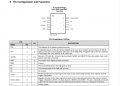
I will describe the pinout here, tell me please if i understood well how everything works or not:
PIN 1: TACH+ is the positive terminal of the schmitt trigger comparator, here i should connect my input signal that goes from 1 to 10 KHz right?
PIN 2: A capacitor placed on this pin will be charged up to VCC/2 by a constant current source of 180 µA typical at the start of every positive half cycle. At the beginning of negative half cycles this capacitor is discharged the same amount at the same rate. So i guess here its similar to the system i developed ( Where u measure the voltage across the capacitor to know the voltage ), on this PIN then i just connect a capacitor to GND right?
PIN 3: See pins CP1 and IN+. On 8-pin devices (8-pin LM2907 and LM2917) these two nodes share a pin and are internally connected.
So what i need to connect here? the RC circuit i calculated by using the formula? or what exactly? : Vo = R1 × C1×VCC× f
PIN 4: emitter of the BJT , here i size the resistor in order to have a certain current, which if i choose a 10k resistor i will get like 0,33mA (which is ok for me, i dont have to drive a load that requires too much current, in fact i just need to read the value of the voltage )
PIN 5: i just tie the collector to power supply , which is 3.3V in my case
PIN 6: supply voltage , which is 3.3V in my case
PIN 7: The inverting input to the high gain op amp, i tie this pin to the emitter, it makes the op amp in buffer configuration no?
PIN 8: GND PIN
what do u think guys? there is something i missing that i didnt understand? how u would ''start'' to size this component or so? thanks all.
I have found out this IC: LM2907 https://share.google/KRJvE2bX6rewz7I17 ( look images below for pinout and typical application )
Vo = R1 × C1×VCC× f In the datasheet there is this formula, so basically i assign VO=3.3V and f = 10KHz and then choose R value to find the capacitance value? right? i need a f-v converter like the one i made 1-10KHz input -> 0-3.3V output.
I will describe the pinout here, tell me please if i understood well how everything works or not:
PIN 1: TACH+ is the positive terminal of the schmitt trigger comparator, here i should connect my input signal that goes from 1 to 10 KHz right?
PIN 2: A capacitor placed on this pin will be charged up to VCC/2 by a constant current source of 180 µA typical at the start of every positive half cycle. At the beginning of negative half cycles this capacitor is discharged the same amount at the same rate. So i guess here its similar to the system i developed ( Where u measure the voltage across the capacitor to know the voltage ), on this PIN then i just connect a capacitor to GND right?
PIN 3: See pins CP1 and IN+. On 8-pin devices (8-pin LM2907 and LM2917) these two nodes share a pin and are internally connected.
So what i need to connect here? the RC circuit i calculated by using the formula? or what exactly? : Vo = R1 × C1×VCC× f
PIN 4: emitter of the BJT , here i size the resistor in order to have a certain current, which if i choose a 10k resistor i will get like 0,33mA (which is ok for me, i dont have to drive a load that requires too much current, in fact i just need to read the value of the voltage )
PIN 5: i just tie the collector to power supply , which is 3.3V in my case
PIN 6: supply voltage , which is 3.3V in my case
PIN 7: The inverting input to the high gain op amp, i tie this pin to the emitter, it makes the op amp in buffer configuration no?
PIN 8: GND PIN
what do u think guys? there is something i missing that i didnt understand? how u would ''start'' to size this component or so? thanks all.
Attachments
-
 48.5 KB Views: 3
 -
 127.8 KB Views: 3


