 Facebook
 Google
 GitHub
 Linkedin
Hello all, I am hoping that somebody can help me with this query.
I have recently purchased an extractor fan which has an integral Humidistat which as I understand it, although there is a constant electrical connection, should only switch on the fan when it detects humidity and stop the fan when the humidity is cleared.
The 2x fans I have tried so far don't appear to work in that way.
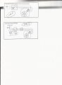
The query I have is the wiring diagrams provided by the manufacturer (see attached)
They suggest that using Diag B, the Humidistat will work but using Diag A will disable the Humidistat but my query is:
Isn't Diag A basically the same wiring as Diag B but without the pull switch and light bulb and therefore should both work the same.
.png")
Regards
Moderators note : cropped image
I have recently purchased an extractor fan which has an integral Humidistat which as I understand it, although there is a constant electrical connection, should only switch on the fan when it detects humidity and stop the fan when the humidity is cleared.
The 2x fans I have tried so far don't appear to work in that way.
The query I have is the wiring diagrams provided by the manufacturer (see attached)
They suggest that using Diag B, the Humidistat will work but using Diag A will disable the Humidistat but my query is:
Isn't Diag A basically the same wiring as Diag B but without the pull switch and light bulb and therefore should both work the same.
Regards
Moderators note : cropped image
Attachments
-
 74.4 KB Views: 10
Last edited by a moderator:


