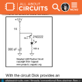
explanation of circuit diagram

Thread Starter

falade47

Joined Jan 24, 2017
178
Please can I get dick capel or anyone to explain how this circuit works..i tried using the component specified on the diagram and it worked as stated..so i tried to see if I could achieve a frequency of 0.25Hz..so I used a higher capacitance of 1300uf, it took a while before the led came on (I suspected the capacitor was charging up) and then it started to oscillate at almost same frequency with the latter
 

Attachments

DickCappels

Joined Aug 21, 2008
10,661
I cannot explain why making the capacitor 4x as large did not make the oscillation 1/4 as fast. The first flash will take longer than the period between subsequent flashes because the first flash starts with zero volts across the capacitor and it has to charge all the way up to the avalanche voltage before the flash occurs. Flashes only partially discharged the capacitor so it can charge back up to the avalanche voltage more quickly on flashes subsequent to the first flash..

Should be no problem to get 100 Hz, but raising the frequency will result in dimmer flashes because unless you use more complex circuitry the capacitor will get smaller, thus making less energy available for each flash.

Connecting it to an external device -one person connected a dynamic speaker in series with the LED and made a metronome.
 

Thread Starter

falade47

Joined Jan 24, 2017
178
I cannot explain why making the capacitor 4x as large did not make the oscillation 1/4 as fast. The first flash will take longer than the period between pulses because the first flash starts with zero volts across the capacitor and it has to charge all the way up to the avalanche voltage before the flash occurs. Between flashes the capacitor is only partially discharged so it can charge back up to the avalanche voltage more quickly.

Should be no problem to get 100 Hz, but raising the frequency will result in dimmer flashes because unless you use more complex circuitry the capacitor will get smaller, thus making less energy available for each flash.
Can I use this as a frequency generator to drive mosfet for a small inverter?
 

DickCappels

Joined Aug 21, 2008
10,661
You can but it probably would not work well. For one thing, the duty cycle is difficult to vary. There are many better methods of driving MOSFET gates.
 
Top