 Facebook
 Google
 GitHub
 Linkedin
This thermoelectric module for cooling system is new for me. I conducted an experiment on Peltier Thermoelectric Module. I want to test how it behaves when I provide certain level of voltage and what would be the current looks like and calculate the power used before designing suitable circuit to control it.
Peltier Thermoelectric Module with max rating: 100W, 20V, 8.5A, deltaT 71DegC
http://uk.rs-online.com/web/p/peltier-modules/6935107/
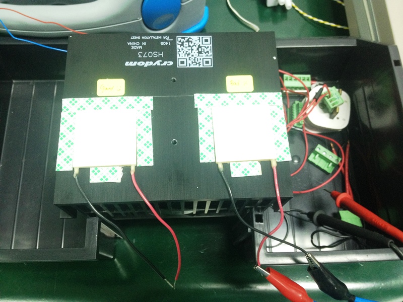
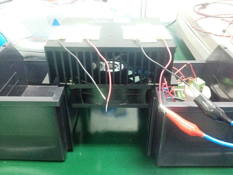
Test Setup: As shown in the picture. Cold side of Peltier faced upwards exposing to ambient. Hot side faced downwards and fan+heat sink was used to dissipate the heat from there.


DC power supply is used to generate DC voltages 12V, 16,V and 18V to Peltier and to measure the current.
Measurement Results:
At 12V, I = 3.54A, P=42.28W
At 16V, I = 4.1A, P=65.6W
At 18V, I=4.5A, P= 81W
At 20V, I= 4.9A, P=98W
Observation:
1. When voltage increases, the current also increases. Thus the calculated power is higher.
2. When first turn on the DC power supply, eg. at 12V, the current reading at first is around 4.1A then gradually drops to 3.54A after 1 minute, and it keeps on decreasing slowly as well. Same observation happened at other voltages.
3. When I touch at the cold side, the current increases. Thus I think that more current is consumed to cool down the heat (from my finger)
4. Eventually one of the thermoelectric modules broken down, found it was open, high impedance. But the last reading was 12V and approx 3.3A. The cold side has turned hot when the moment current reading became 0A.
Questions:
Q1: Why the measured current is higher when the voltage increases? Assume the ambient is about the same, so the power used to cool down the ambient heat should be the same, right?
Q2. I didn't not exceed the max voltage 20V, and the current measured was 3.3A still far below 8.5A. What makes the thermoelectric module broken? Is it because I must always put hot object at cold side to keep this module working?
Q3. Is this how the thermoelectric module behaves? My application is to use this module to cool down water tank. So when the water tank is hot, then only I turn on the PWM to drive the thermoeletric module?
Hope to get some answer to help me understand more on its behavior. Thanks.
Peltier Thermoelectric Module with max rating: 100W, 20V, 8.5A, deltaT 71DegC
http://uk.rs-online.com/web/p/peltier-modules/6935107/
Test Setup: As shown in the picture. Cold side of Peltier faced upwards exposing to ambient. Hot side faced downwards and fan+heat sink was used to dissipate the heat from there.
DC power supply is used to generate DC voltages 12V, 16,V and 18V to Peltier and to measure the current.
Measurement Results:
At 12V, I = 3.54A, P=42.28W
At 16V, I = 4.1A, P=65.6W
At 18V, I=4.5A, P= 81W
At 20V, I= 4.9A, P=98W
Observation:
1. When voltage increases, the current also increases. Thus the calculated power is higher.
2. When first turn on the DC power supply, eg. at 12V, the current reading at first is around 4.1A then gradually drops to 3.54A after 1 minute, and it keeps on decreasing slowly as well. Same observation happened at other voltages.
3. When I touch at the cold side, the current increases. Thus I think that more current is consumed to cool down the heat (from my finger)
4. Eventually one of the thermoelectric modules broken down, found it was open, high impedance. But the last reading was 12V and approx 3.3A. The cold side has turned hot when the moment current reading became 0A.
Questions:
Q1: Why the measured current is higher when the voltage increases? Assume the ambient is about the same, so the power used to cool down the ambient heat should be the same, right?
Q2. I didn't not exceed the max voltage 20V, and the current measured was 3.3A still far below 8.5A. What makes the thermoelectric module broken? Is it because I must always put hot object at cold side to keep this module working?
Q3. Is this how the thermoelectric module behaves? My application is to use this module to cool down water tank. So when the water tank is hot, then only I turn on the PWM to drive the thermoeletric module?
Hope to get some answer to help me understand more on its behavior. Thanks.


