Expanded scale volt meter

Thread Starter

Ian Harris

Joined May 4, 2016
26
I've spent the entire afternoon fruitlessly trying to figure out how to do what I want to do, even though I know it's very common. Now I need someone who actually knows what they are doing to point me in the right direction.
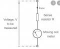
I have an analog voltmeter installed in a (vintage) device, that I have discovered by trial and error produces full deflection with 3V. I have a two cell LiFeP04 battery in it, and I would like to connect it to the voltmeter so it shows zero when the battery reaches about 5.6V (2.8V per cell) and full deflection when the battery is about 7.3V (2.65V per cell).
I've found a post that shows how to do it for a car battery using a zener diode, a resistor and a pot. Looks ideal. I have been trying to figure out what values I need for the pot and the resistor using this circuit simulator but I have no idea what the values for the zener diode mean in the simulator. In the circuit description it says that the zener voltage controls the low voltage, so I presumably I need a zener as close as I can get to 5.6V, but I don't know how to specify that in the simulator. Trying random combinations has got me nowhere.
Can anybody please advise me what values I need for the resistor and the pot?
All assistance gratefully received.
:-(
 

ericgibbs

Joined Jan 29, 2010
18,766
hi Ian,
Which sim program are you using.?
Do you have a rough sketch to post.?

It sounds as though you are trying for a 5.6V offset from 0V.
To give a reading of 5V6 thru 8V6 on the meter.

E

Added the Car version image.

EG 886.png
EG 884.pngEG 885.png
 
Last edited:

Thread Starter

Ian Harris

Joined May 4, 2016
26
@ericgibbs, thanks for the quick reply. The screenshot you have added is from the sim I was trying to use. I found the example circuit as shown in the screenshot. I assumed the one I wanted was the "voltage reference" example, although it doesn't look much like the car example, so I'm a bit lost. Did I mention I barely know how to spell "electronics"?...

This is what I ended up with. I made the resistors variables so I could experiment with different combinations. In this shot I managed to get the output voltage (assuming I've got the voltmeter in the right place) to close enough to 3V when the battery is at 7.2V.
1633954571469.png

But when the battery voltage drops to 5.6V the output drops to 2.4V, not zero or even close
1633954984070.png

I have found that by reducing the 3k resistor to something very low (like a few ohms) then the output drops to near zero, but then of course no amount of fiddling with the other resistor gets it back up to 3V again.

:-(
 

ericgibbs

Joined Jan 29, 2010
18,766
hi Ian,
The problem is the 3K resistor,
With the 4k in series with that 3K, you have a voltage divider.

So if your Battery was say 5.6V , the Meter would have 5.6V* (3k/7k) across its terminals. ie: 2.4V. in fact what you are seeing.

If you look at the Car version the Meter is in series with the Zener.

I will do a quick sketch.

E
 

ericgibbs

Joined Jan 29, 2010
18,766
Hi Ian,
Do you know what is the actual resistance of the voltmeter.

The problem is you are trying to measure from 0v to 3V from a Change of only 7.2v-5.6v = 1.6V

Not possible..:( with that method
E
 

Thread Starter

Ian Harris

Joined May 4, 2016
26
@ericgibbs thanks for the reply. I tried creating a circuit more like the car one and ended up with this.
1633995253736.png

I think it's right but I'm pretty new at this. With the battery at 7.2V the voltage on the meter would not go above 1.6V (and 5.6v input gave near enough to zero) until I started playing with the zener parameters. I found that if I reduced the breakdown voltage to four, I could then adjust the variable resistor so the output was near enough to 3V, but now with the battery at 5.6V the output is around 1.6v, so it seems I can't have my cake and eat it.

So you comment about measuring a 1.6v deflection with a 3v meter makes sense. It just can't happen. It's like pouring 1.6 litres of fluid into a 3 litre container. It's never going to get more than a bit over half full. Unless you start with 1.4l already in it.

So this ain't the solution. Is there one? A simple one, that is... with a transistor and a couple of resistors? I had a look on the net and everything I found used an IC chip of some sort. Seems like overkill to me for what I want to do. I don't need 0.1% accuracy, 5% would be fine, even 10%.

:-\
 

ericgibbs

Joined Jan 29, 2010
18,766
hi Ian,
Inside the Meter there should be a resistor in series with the coiled armature.
Can you carefully open up the Meter and check/post the resistance value.?

The idea would be choose an internal resistor that limited the current thru the coil, so that 0V thru 1.65V would give a FSD [ full scale deflection] ie: 0V to 1.65V.

Once that is done we could use a variant of the Car circuit method

E
EG 892.png
 

Attachments

Last edited:

MisterBill2

Joined Jan 23, 2018
18,167
There are quite a few devices that will provide a stable 5 volts that you can use as the negative reference for your meter. Then it can read directly the amount over 5 volts as the cell voltage. But all of the arrangements will draw some additional current constantly and this will be a battery drain.
And a caution about most zener diodes is that the voltage drop across the diode is quite dependent on current at the lower current levels.
 

ericgibbs

Joined Jan 29, 2010
18,766
hi Bill,
The TS has an old analog 0V to 3Vdc [FSD] voltmeter and he wants it show 0v to 1.6Vdc [FSD]

The 1.6V is the Slope of his battery pack voltage 7.2V down to 5.6V

E
 

MisterBill2

Joined Jan 23, 2018
18,167
Many older analog meters are a bit less accurate towards the end of the scale. And in addition, that would require a calibration in percent of full charge, which is not quite a linear function. It would also be useless for any other application. Besides that there are a whole lot more 5 vol references available than 5.60 volt references.
Depending on the meter construction it may be quite simple to adjust the two springs to give the desired span and zero point. For certain, if a full scale deflection requires 3 volts,, some mechanical adjustment will be needed to get a 1.60 volts full scale reading, no matter what passive devices are used.
If the TS wants to use an op-amp then the solution is simple.
 

ericgibbs

Joined Jan 29, 2010
18,766
hi Bill.
I have asked him to see if he can access the internal current limiting resistor, we can then change the scaling fro 3vFSD to 1.62vFSD
E
 

MisterBill2

Joined Jan 23, 2018
18,167
I doubt that there is an internal current limiting resistor. I had a set of antique volt meters and they just had a coil of quite fine wire that formed the electromagnet. It was an entirely different scheme than those more recent meter movements. And it was not very linear . That is why I suggested a bit of a different scheme.
Also, folks do need to realize that the zener diode also has a curve as it goes into reverse conduction. It is not a square corner, quite unlike a good reference device.
 

Thread Starter

Ian Harris

Joined May 4, 2016
26
@ericgibbs and @MisterBill2 thanks for your valuable input. Much appreciated.

Here are a couple of pics of the meter. The device itself (a R/C transmitter for model planes) dates from circa early '80s, (certainly no later but possibly earlier) so presumably the meter dates from then too. Looking inside it will be a problem as a) it appears to be glued in (although it's a bit loose) and b) I can't see any easy way of disassemling it. Maybe it clicks together? Don't know... I don't want to destroy it as I like the "retro" look of it. I might be able to get another similar looking modern one that would work better, but I'm saving that option for later.

IMG_20211013_114728_HDR.jpgIMG_20211013_114752_HDR.jpg

Vis accuracy and voltage curves, I guess I should explain that all I need it to do is tell me whether there is enough charge in the battery to safely fly, so all I need to see is that the needle is basically in the top half of the gauge. If it's below half I might think twice.

If it takes something like an opamp to get it to work, happy to do that, given that using passive components seems to be more trouble than it's worth. Can you point me to a suitable circuit?

Thanks,
Ian
 

Sensacell

Joined Jun 19, 2012
3,432
Then it's a 1 milliamp approx. full-scale movement.
Unless you can get inside and change the resistor (if it has one) you are not going to get a 1.6V full-scale deflection without an opamp in the mix.

Look into using the TL431 instead of a Zener, it will make this MUCH more accurate and easier to calibrate.
 

Thread Starter

Ian Harris

Joined May 4, 2016
26
@Sensacell thanks for the reply. I confess I am hopelessly out of my depth now though. I looked at a few sites that talked about the TL431 but I don't really understand what it is doing. Several places say that it is a better zener diode. That's good but my understanding is that a zener diode is not going to solve my problem. Another site said that it is like a zener but the output voltage can be controlled. What it didn't say was whether the output voltage could be greater than the reference voltage. It does appear to have an opamp inside it though, so maybe?...
Thanks,
Ian
 

ericgibbs

Joined Jan 29, 2010
18,766
hi Ian,
As we agreed, to display 1.62V FSD on a 3V FSD is not possible.
I would settle for 5.6V == 0V on the meter and 1.62V is just over 50+%.
Mark the meter plastic face at the 1.62V point, using a RED felt tip pen.

Have you decided to go for a 5V6 Zener or TL431, which do you you have on the Bench.??
E
 
Top