Expanded scale volt meter

ericgibbs

Joined Jan 29, 2010
18,849
hi Ian,
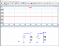
If you can open up the meter and/if the calibrating resistor is accessible, changing it to a 1k2, should set the meter current 1mA at 1.6V. FSD

E
 

Attachments

Last edited:

Ian0

Joined Aug 7, 2020
9,818
I tried this with a zener on a 12V lead acid battery with a 10V zener as a reference so that it read 10V to 15V.
The zener voltage changed so much as the current fell, that it was unusable at the low end of the scale.
I replaced the zener by a 10V LM4040 and the result was far better. (Unlike a TL431 it needs no external resistors)
I’d suggest a 5Volt LM4040 and have it read 5V to 8V, putting the 1.6V range of interest at the centre of the scale.
 

MisterBill2

Joined Jan 23, 2018
18,519
An op-amp would use a simple inverting circuit with a variable resistor to set the gain by adjusting the feedback from the output to the inverting input. Then the zero point would come from an adjustable resistor feeding the non-inverting input. The challenge will be regulating the supply voltage for the op-amp. And since it would be an active device consuming power you will need a button to turn it on to do the battery voltage check.
 

Thread Starter

Ian Harris

Joined May 4, 2016
26
@Ian0 I have no idea what that circuit is or does, but I do know the resistance of the meter is 2.8k. Could you please fill in some values for the resistors and what the transistors are? Also the zener diode, if that's what it is. Thanks.

@ericgibbs I'll have another look tomorrow. Getting late here. Could an op amp be used to amplify the voltage? Would that be an easier solution? Thanks.
 

crutschow

Joined Mar 14, 2008
34,452
Below is the LTspice simulation of a circuit that should do what you want.
It uses a TL431 2.5V reference and one LMC6484 rail-rail op amp quad package.
It may seem a little complex, but it is the simplest I could come up with to give the voltage ranges you want with good accuracy.

Op amp U1a is configured for a non-inverting gain of 2.24 that amplifies U2's 2.5V reference voltage to 5.6V.

Op amp U1b is configured as a differential amp with a gain of 1.74.
Since U1b's negative supply is ground, its output can't go negative from the amplified reference voltage, so the output (yellow trace) stays at 0V until the battery voltage (green trace) is equal to U1a's output of 5.6V.
It then amplifies the offset battery voltage by a gain of 1.74 to the meter, giving a 3V output when the battery is at 7.3V.

The circuit's maximum full scale draw from the battery at maximum voltage is a little over 7mA including the meter.

1634147699790.png
 
Last edited:

Ian0

Joined Aug 7, 2020
9,818
It's called a "current mirror" because the current that comes out of Q1 is the same as whatever current goes into Q2. Looks sort of like it has been "reflected"!
I don't know how accurate it needs to be, but I suspect that this might be at least as good as the meter. You can make R1 adjustable for fine-tuning.
Choice of transistor - anything you have two off out of the same batch! I've quoted BCV61 because it is a matched pair.
(Stating the obvious here - R2 is the meter)

current_mirror.png
 

crutschow

Joined Mar 14, 2008
34,452
Ian0 beat me to it.
Below is my LTspice simulation of Ian0's circuit in post #24 using a precision 5V, low-current, shunt reference (emulated Zener).
It is much simpler than my circuit, but is slightly more temperature sensitive due to the change is base-emitter voltage of the transistors with temperature.
You likely will have to tweak the value of R1 (or make it a 2k pot) to adjust it to the desired full-scale.

To use a cheaper part, you could likely use the LM4040 (5V) reference suggested by Ian0 (I don't have a Spice model in my library for that).
It's more accurate and stable than a Zener diode.
Also the 5V reference gives a meter turn on voltage closer to the desired 5.6V than a 5.1V Zener.

1634150031617.png
 
Last edited:

Ian0

Joined Aug 7, 2020
9,818
Ian0 beat me to it.
Below is my LTspice simulation of Ian0's circuit in post #24 using a precision 5V, low-current, shunt reference (emulated Zener).
It is much simpler than my circuit, but is slightly more temperature sensitive due to the change is base-emitter voltage of the transistors with temperature.
You likely will have to tweak the value of R1 (or make it a 2k pot) to adjust it to the desired full-scale.

To use a cheaper part, you could likely use the LM4040 (5V) reference suggested by Ian0 (I don't have a Spice model in my library for that).
It's more accurate and stable than a Zener diode.
I looked at the picture of the meter and made a judgement of what level of accuracy was really required!
If it were just a bit higher voltage the zener tempco and the Vbe tempco might just cancel out.
[Edit] but as it stands it might just compensate for the tempco of the terminal voltage of the battery!
 
Last edited:

Thread Starter

Ian Harris

Joined May 4, 2016
26
@Ian0, @crutschow, @ericgibbs thank you all for you valuable advice, it is greatly appreciated.

I will try ian0's circuit as it has the least number of components, so I have a sporting chance of getting it to work!

Ian0 is also correct about the level of accuracy. To be honest I only really need to know if the battery has enough power left for another flight (it's a radio control transmitter), so probably above half way is good, above one third might be okay, below that I should probably pack up and go home. A flight lasts typically about 6 to 7 minutes, so the transmitter is switched on for no more than about ten minutes at a time usually, the rest of the time it's switched off, so current drain is probably not really an issue either. I usually only do about 3 of 4 flights on a good day, so a full charge is usually good for several flying days. But I have been known to forget, hence my desire to have the meter working!

Once again thanks to all who took the time to offer advice. It's all been very helpful and I've learned a bit along the way too.

;-) Ian
 

crutschow

Joined Mar 14, 2008
34,452
I will try ian0's circuit as it has the least number of components, so I have a sporting chance of getting it to work!
Given the moderate level of accuracy you need, Ian0's circuit should be quite sufficient (especially if you use the LM4040 5V voltage reference in place of the Zener).
I would use a 2kΩ pot for R1 to allow for easy adjustment of the desired voltage range.
 

crutschow

Joined Mar 14, 2008
34,452
Addendum:
Use about a 440Ω resistor in series with the trimpot so you don't accidentally turn the pot to zero and zap the transistor.
Revised schematic below:
Red trace is the voltage across the simulated meter resistance.
Horizontal scale is the battery voltage.

1634191142005.png
 
Last edited:

Thread Starter

Ian Harris

Joined May 4, 2016
26
@crutschow thanks for the tips. I've just returned from my local electronics shop (Jaycar), and they didn't have a LT1634-5, nor do they have an LM4040, nor a TL431. So not terribly helpful. I did a search on their site for "precision micropower shunt voltage reference" and got many hits, but most of them were voltage regulators, which I'm assuming is not the same thing? So I tried just searching for "voltage reference" and found one, but it's 2.5V not 5V. I can order one online for about $1, and pay about $12 for postage. Push comes to shove I guess I'll have to bite the bullet and pay the money. Unless you have a better idea...

:-( Ian
 

Sensacell

Joined Jun 19, 2012
3,449
Yeah, there are just too many parts today for a "shop" to have a meaningful stock to build from.

You need to order them from a monster distributor like Digikey.
 

Ian0

Joined Aug 7, 2020
9,818
@crutschow thanks for the tips. I've just returned from my local electronics shop (Jaycar), and they didn't have a LT1634-5, nor do they have an LM4040, nor a TL431. So not terribly helpful. I did a search on their site for "precision micropower shunt voltage reference" and got many hits, but most of them were voltage regulators, which I'm assuming is not the same thing? So I tried just searching for "voltage reference" and found one, but it's 2.5V not 5V. I can order one online for about $1, and pay about $12 for postage. Push comes to shove I guess I'll have to bite the bullet and pay the money. Unless you have a better idea...

:-( Ian
Put the 5.1V zener in, if it’s not close enough then think about ordering an LM4040!
 

Thread Starter

Ian Harris

Joined May 4, 2016
26
@Sensacell Yeah, and I live in a small country town in Northern NSW Australia, (pop. 40k) so the local shop is tiny. Just for fun I looked up Digikey Australia, and there is one, so I tried ordering a LM4040 from them. It was a couple of dollars, but postage was from the US and was AUD$24. So no Aussie stock at all apparently. There is another big company here that I generally use when I want parts, Element14. (Silicon, if you're wondering). They're usually pretty good, and they do have the LM4040 in stock. aud$15 postage. I guess I can't complain too hard though, it probably costs them that to get someone to pick the part, put it in an envelope, write my address on it and stick a stamp on. c'est la vie, as the French say.

;-)
 
Top