 Facebook
 Google
 GitHub
 Linkedin
Hi,
Have been struggeling for some weeks. but i do need some help.
have tried to get correct id from LCD but it's not replying correct.
I use PlatformIO for VS-code. I use
platform = espressif32
board = esp32-s2-saola-1
framework = arduino
monitor_speed = 115200
upload_port = COM4
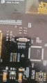
Display is a
Serial SPI I2C 10.1"TFT LCD Module Dislay w/RA8876,OPTL Touch Panel
Chip i not RA8876 but LT7683 , can be with either one.
have this code for reading out the id,
i use
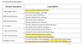
#define TFT_MISO 13
#define TFT_MOSI 11
#define TFT_SCK 12
#define TFT_CS 10
#define TFT_RST 9 // Reset
#define TFT_BUSY 8 // Busy pin (if nessesary)
Have tried with many different setting for delays, and mode form 100 khz to 10mhz SPI mode 0-1-2-3
Have read that display ID should allways be 0x80.
Edit, translate from danish
Have been struggeling for some weeks. but i do need some help.
have tried to get correct id from LCD but it's not replying correct.
I use PlatformIO for VS-code. I use
platform = espressif32
board = esp32-s2-saola-1
framework = arduino
monitor_speed = 115200
upload_port = COM4
Display is a
Serial SPI I2C 10.1"TFT LCD Module Dislay w/RA8876,OPTL Touch Panel
Chip i not RA8876 but LT7683 , can be with either one.
have this code for reading out the id,
Code:
void setup() {
   // Aktiver pull-up modstand på GPIO0 og GPIO2 for normal start
   pinMode(0, INPUT_PULLUP);  // GPIO0 input with pull-up
   pinMode(2, INPUT_PULLUP);  // GPIO2 input with pull-up

   // Aktivate pull-down on GPIO15 for normal start
   pinMode(15, INPUT_PULLDOWN);  // GPIO15 as input with pull-down

  // Start seriel monitor
  Serial.begin(115200);
  //pinMode(TFT_CS, OUTPUT);
//digitalWrite(TFT_CS, HIGH);  // starts HIGH

  delay(1000);
  Serial.println(" Initialiserer screen...");
//testSPI();
Serial.println(" Resetting LT7683...");

pinMode(TFT_RST, OUTPUT);
digitalWrite(TFT_RST, LOW);
delay(50);  // Hold LOW i least 50ms
digitalWrite(TFT_RST, HIGH);
delay(100); // wait for stabilisering

Serial.println("✅ LT7683 Reset Done!");


SPI.begin(12, 13, 11, 10);
SPI.beginTransaction(SPISettings(1000000, MSBFIRST, SPI_MODE1)); //1 MHz, SPI mode 1

pinMode(TFT_CS, OUTPUT);
digitalWrite(TFT_CS, HIGH);
delay(10);


digitalWrite(TFT_CS, LOW);
delayMicroseconds(50);  // wait some before SPI-transfer

SPI.transfer(0xD0);  // Read Command
delayMicroseconds(10);
SPI.transfer(0x00);  // Read Chip ID Register
delayMicroseconds(10);
uint8_t chipID1 = display.readRegister(0x00);
delay(10);
uint8_t chipID2 = display.readRegister(0x00);

Serial.print("LT7683 Chip ID (first reading): 0x");
Serial.println(chipID1, HEX);
Serial.print("LT7683 Chip ID (second reading): 0x");
Serial.println(chipID2, HEX);

delayMicroseconds(50);  // wait before CS HIGH
digitalWrite(TFT_CS, HIGH);
SPI.endTransaction();

Serial.print("LT7683 Chip ID: 0x");
Serial.println(chipID1, HEX);

if (chipID1 == 0x80) {
    Serial.println("✅ LT7683 is correct initialiseret!");
} else {
    Serial.println("⚠ ERROR! Check wires");
}#define TFT_MISO 13
#define TFT_MOSI 11
#define TFT_SCK 12
#define TFT_CS 10
#define TFT_RST 9 // Reset
#define TFT_BUSY 8 // Busy pin (if nessesary)
Have tried with many different setting for delays, and mode form 100 khz to 10mhz SPI mode 0-1-2-3
Have read that display ID should allways be 0x80.
Edit, translate from danish
Last edited:
 SPI init færdig


