 Facebook
 Google
 GitHub
 Linkedin
Hello guys.
This Will be a Stupid question, one i can't find solution to on google.
If schematics are needed it will follow if don't know how to fix it.
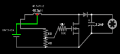
In short I have a center-tap inductor connected to STGW38IH130D Igbt(it's the only chip i have that worked with the powersupply i had, a acdc 17v 1A adapter)... Accross the Collector-Emitter there is a diode and a 2.2mF 25V electrolitic cap, all in all to make a booste circuit to run a motor, with a potentiameter at the Gate to change the switching speed of the igbt(i guess) to change the output voltage to run a motor... It works beautifully.
Now my question:
I swopped to a 19V 3.42A adapter, it runs the motor just fine normally, but when i switch to the boost circuit, the igbt just turns on an off at 1hz, seems like error message from the chip, since my igbt is a 1.3kV Vce & 33A Ic chip the problem must be at the Gate voltage, Is the oscillating voltage in the inductor too much for the Gate, or what? Why is it going on off at 1hz. It's NOT shitching.
I did add a 19V(16v+3v) zenor diodes in series with the Gate and potentiameter but now neither power supplies work.
What is the error message from the chip?
How do i fix it?
Note: i can't edit the circuit much except at the bottom side where the wires are since top side of the thread board is glued closed.

I hope someone can share some light on this.
This Will be a Stupid question, one i can't find solution to on google.
If schematics are needed it will follow if don't know how to fix it.
In short I have a center-tap inductor connected to STGW38IH130D Igbt(it's the only chip i have that worked with the powersupply i had, a acdc 17v 1A adapter)... Accross the Collector-Emitter there is a diode and a 2.2mF 25V electrolitic cap, all in all to make a booste circuit to run a motor, with a potentiameter at the Gate to change the switching speed of the igbt(i guess) to change the output voltage to run a motor... It works beautifully.
Now my question:
I swopped to a 19V 3.42A adapter, it runs the motor just fine normally, but when i switch to the boost circuit, the igbt just turns on an off at 1hz, seems like error message from the chip, since my igbt is a 1.3kV Vce & 33A Ic chip the problem must be at the Gate voltage, Is the oscillating voltage in the inductor too much for the Gate, or what? Why is it going on off at 1hz. It's NOT shitching.
I did add a 19V(16v+3v) zenor diodes in series with the Gate and potentiameter but now neither power supplies work.
What is the error message from the chip?
How do i fix it?
Note: i can't edit the circuit much except at the bottom side where the wires are since top side of the thread board is glued closed.
I hope someone can share some light on this.


")


