Facebook
 Google
 GitHub
 Linkedin

Hey, I am changing out my PCB to use SMD resistors instead of THT resistors.
I am fairly new to electronics.
Schematics:
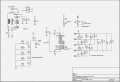
The SMD resistors I plan to use are different values of the JLCPCB Basic Part UNI-ROYAL 0805 resistors, for example this one: https://jlcpcb.com/partdetail/18159-0805W8F1500T5E/C17471.
The resistor I linked is rated at 125mW, I want to check that I don't exceed the maximum wattage rating.
I read on this website: https://www.electronics-tutorials.ws/resistor/res_7.html
"it is always better to select a particular size resistor that is capable of dissipating two or more times the calculated power". So I need to check that the power across my resistors are not greater than 75mW.
Circuit will be powered with 5V (USB-C).
To save the pain of needing to check all resistors, here is what I did:
I have some resistors (for example the pullup resistors) that will have a voltage drop of 5V.
So in worst case the voltage drop across a resistor is 5V.
As P=V^2/R where V is the voltage drop across the resistor: The only resistors that would need some more careful calculations (in terms of their actual voltage drop) are those with
R<=(5^2)/(75*10^-3)=333.3...
as the maximum power should be 75mW and the maximum voltage across any resistor would be 5V.
This means that I need to double check any resistor below about 333Ohm - I have 150Ohm (R2-R6) resistors and a 10Ohm resistor (R8) that are in the danger zone.
1) Calculations for R8
If we look at R8, voltage only passes through it when SW1 is closed. It passes from VCC=5V through R7 and R8:
I = 5/(R7+R8)
VR7 (voltage over resistor R7)=R7*I=R7*(5/(R7+R8))=2.2×10^3×(5)/(2.2×10^3+10)=4.977 V
So no need to worry about R8, the voltage over it is 0.02V - the power over it is (0.02^2)/10=0.04mW.
2) Calculations for R2-R6
Regarding this part of the circuit. I am using a technique called Charlieplexing, meaning at any instantaneous moment, I will only have ONE of the LEDs (D1-15) turned on at a time. Two of the PB0-1/PA7-PA5 pins are set to output high and the other to output low. Others are floating. Led forward voltage is min 1.8V.
Pin logic level is =VCC.
As the resistor values are the same, their voltage drop is also the same, so (5-1.8)/2=1.6V drop over each 150Ohm resistor.
So the power over each resistor (1.6^2)/150=17mW
Therefore no need to worry about the resistor wattage being exceeded.
My question is basically if my reasoning is correct and I indeed don't need to worry. I don't have enough electronics experience to trust myself.
I am fairly new to electronics.
Schematics:
The SMD resistors I plan to use are different values of the JLCPCB Basic Part UNI-ROYAL 0805 resistors, for example this one: https://jlcpcb.com/partdetail/18159-0805W8F1500T5E/C17471.
The resistor I linked is rated at 125mW, I want to check that I don't exceed the maximum wattage rating.
I read on this website: https://www.electronics-tutorials.ws/resistor/res_7.html
"it is always better to select a particular size resistor that is capable of dissipating two or more times the calculated power". So I need to check that the power across my resistors are not greater than 75mW.
Circuit will be powered with 5V (USB-C).
To save the pain of needing to check all resistors, here is what I did:
I have some resistors (for example the pullup resistors) that will have a voltage drop of 5V.
So in worst case the voltage drop across a resistor is 5V.
As P=V^2/R where V is the voltage drop across the resistor: The only resistors that would need some more careful calculations (in terms of their actual voltage drop) are those with
R<=(5^2)/(75*10^-3)=333.3...
as the maximum power should be 75mW and the maximum voltage across any resistor would be 5V.
This means that I need to double check any resistor below about 333Ohm - I have 150Ohm (R2-R6) resistors and a 10Ohm resistor (R8) that are in the danger zone.
1) Calculations for R8
If we look at R8, voltage only passes through it when SW1 is closed. It passes from VCC=5V through R7 and R8:
I = 5/(R7+R8)
VR7 (voltage over resistor R7)=R7*I=R7*(5/(R7+R8))=2.2×10^3×(5)/(2.2×10^3+10)=4.977 V
So no need to worry about R8, the voltage over it is 0.02V - the power over it is (0.02^2)/10=0.04mW.
2) Calculations for R2-R6
Regarding this part of the circuit. I am using a technique called Charlieplexing, meaning at any instantaneous moment, I will only have ONE of the LEDs (D1-15) turned on at a time. Two of the PB0-1/PA7-PA5 pins are set to output high and the other to output low. Others are floating. Led forward voltage is min 1.8V.
Pin logic level is =VCC.
As the resistor values are the same, their voltage drop is also the same, so (5-1.8)/2=1.6V drop over each 150Ohm resistor.
So the power over each resistor (1.6^2)/150=17mW
Therefore no need to worry about the resistor wattage being exceeded.
My question is basically if my reasoning is correct and I indeed don't need to worry. I don't have enough electronics experience to trust myself.