EMI Filter Simulation in LTSpice

Thread Starter

sasistel

Joined Nov 10, 2017
4
Hey there!

I've been trying to properly get the AC response of an EMI filter using LTSpice. To ensure that I was simulating my design correctly, I have taken from this paper (https://www.diva-portal.org/smash/get/diva2:536143/FULLTEXT01.pdf) a proposed filter and simulated it to see if I get the same result.

This is the expected response:
filt_response.JPG

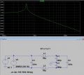
This is my circuit on LTSpice and the response
lts_filt.JPG lt_filt_response.JPG

The response has nothing to do with the paper results and I'm wondering if there is something off with my simulation. Does anyone have any insight?

I've also attached the spice simulation.

Kind regards!
 

Attachments

kubeek

Joined Sep 20, 2005
5,795
I guess you should include the lisn and measure there? Also, you should be introducing common mode exciration, not differential mode. Think about what that graph represents and what would you do to measure that on a real circuit.
 

Thread Starter

sasistel

Joined Nov 10, 2017
4
I guess you should include the lisn and measure there?
Is a model of the LISN really necessary for the simulation?

In the past few days I've been simulating other configurations of EMI filters (including ferrite beads on each of the power lines) and the simulation with the parameters set as in the .asc of the original post gave back results that were really close to what I could measure on a spectrum analyzer.
 

neonstrobe

Joined May 15, 2009
190
I suspect that you are not allowing for real components. Inductors have self-capacitance that lets RF through unless specifically made for low capacitance (e.g. wave wound, spaced turns etc) which tends to limit HF rejection.
 

kubeek

Joined Sep 20, 2005
5,795
Still, exactly 6db reduction tells me you are measuring some bogus value and not the attenuation of the common mode filter. What is v(n001)?
 

Thread Starter

sasistel

Joined Nov 10, 2017
4
second_order_filt_sim.JPG

For instance, here is an example of filter that I've simulated on LTSpice and during the real life measurments I got back very similar results.
 

ebeowulf17

Joined Aug 12, 2014
3,307
I suspect that you are not allowing for real components. Inductors have self-capacitance that lets RF through unless specifically made for low capacitance (e.g. wave wound, spaced turns etc) which tends to limit HF rejection.
I'm guessing this is a huge part of the problem. I recently went through something similar, trying in vain to get simulated EMI filter performance to approximate real world EMI filter performance.

I too mixed up common mode and differential mode injection and measurement at first, but even after fixing that, my models were nowhere close to reality.

I didn't know how to build realistic real world models of the necessary components and eventually gave up on sims for EMI filter simulation. Hopefully the thread starter will do better than I did!
 

giraybalci

Joined Mar 15, 2018
1
A late answer!

The simulation result that you see is the voltage divider voltage by the 560p capacitors. It is -6dB, which is basically half the input voltage. The reason is that when you click a node in LTSpice, it shows the voltage with respect to the ground node. The ground is selected as EARTH in your simulation. When you apply a voltage between L-N and use equal Y capacitors, measurement will always yield in -6dB irrespective of filter values.

So why it is changing with frequency?
(even though it is minuscule)
I believe i read it somewhere but could find right now. Even if you perfectly couple the inductors in LTSpice with k=1, it is k=0.99999... something. I suspect that is the reason. With a tiny leakage inductance, node1 voltage changes with frequency.

So how would you simulate common mode noise?
In this configuration you apply a voltage source differentially. So common mode filter is basically pointless. If you make a transient analysis with your circuit you can see there is no current flowing in/out off your EARTH wire (hold ALT key + click EARTH wire).

To see performance of the CM filter you can apply a noise (v source) between one of the line-neutral and EARTH. (shown in attachment). Now it seems like a differential mode filter. And perfectly fine. After all, in both filter configurations you have an inductor and capacitor which creates a resonance and 2nd order low pass filter.
 

Attachments

Thebat

Joined Dec 4, 2018
2
Bordodynov, it seems to me that you are measuring this circuit incorrectly. Generally, the load is the source of the EMI, for instance, a switch-mode power supply in a PC or a DC brushless fan in a piece of equipment. You want to measure the frequency response at the AC input, agree?
 

Bordodynov

Joined May 20, 2015
3,179
Bordodynov, it seems to me that you are measuring this circuit incorrectly. Generally, the load is the source of the EMI, for instance, a switch-mode power supply in a PC or a DC brushless fan in a piece of equipment. You want to measure the frequency response at the AC input, agree?
What was the question, such is the answer! You can check the filtering of impulse noise, but for this you need to know what kind of interference. Believe me, I can do it. When I need this, I am doing the right analysis.
 

Thebat

Joined Dec 4, 2018
2
I have a need for an EMI filter to eliminate DC brushless fan noise from my +24V DC supply. Attached is a simulation of a Qualtek 84910003 filter I purchased. Haven't received the filter yet. They gave the component values in the datasheet. I haven't been able to accurately simulate their performance data though. Apparently they use CISPR 17 0.1 ohm/100 ohm measurement. I guessed at some component parameters. Maybe I'm missing some parasitics or just don't have the source and loads configured correctly. This would be a great starting point EMI filter design if I could get this simulation worked out. The circuit is currently configured differential, but it should be easy to change it to CM. I plan on actually measuring the filters to see if I can match the datasheet numbers when I receive them. I'd like to get to the point where I could confidently design my own filters, so I can minimize the component sizes. I'll use COTS filters when I can for cost and time savings; however the designs I work on are often SWAP constrained.
 

Attachments

Top