Facebook
 Google
 GitHub
 Linkedin
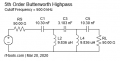
Just rebuilt and rehung my Vibroplex Par EF-SWL 45' end fed sloper antenna for my Icom R-75 all band receiver. On the radio input, I am also using an MFJ-1040C 1.8 - 54 MHz combination preamp, filter and antenna tuner. My problem is that ~100' from the antenna is a 3 phase power distribution feeder. RG-8 coax to the antenna. It is grounded at the radio through the circuit safety ground and also grounded from the balun to a driven dedicated earth ground. On the low frequencies, the hum is horrible from ~1.25MHz and down. Irritating from 1.25 - ~1.35-1.45. The obvious solution is a Hi-Pass input filter.
For comparison: On my Icom IC-7410 (which is also an all-band receiver) it is not as bad on the 135' off-center fed 6 - 80M dipole and near-zero on the 10M vertical. Yes orientation does make a difference. Much better input filtering.
How much attenuation would this add to the overall input? Any practical advice or recommendations?