Facebook
 Google
 GitHub
 Linkedin
Hello World,
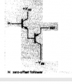
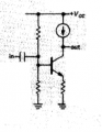
Im reading the book "the art of electronics - horowitz hill", There is a part of the book wich it has "bad circuits", i would like to know whats the problem in that circuits(check pictures),
Whats wrong and why in each circuit?
Thank you all!!!!

[pic 1]

[pic 2]

[pic 3]
Im reading the book "the art of electronics - horowitz hill", There is a part of the book wich it has "bad circuits", i would like to know whats the problem in that circuits(check pictures),
Whats wrong and why in each circuit?
Thank you all!!!!
[pic 1]
[pic 2]
[pic 3]