Electronic Circuit

Thread Starter

Shaggy74

Joined Oct 20, 2017
36
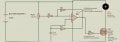
Hi, I have put together the cct shown below, I have changed it slightly by including a 10v motor and a push button on/off switch. I have also included 2 x 9v batteries for the power source. Having proven the cct works I am concerned as the temperature of the 2 9v batteries get extremely hot, could anyone explain why this is happening? Thank you in advance
 

Attachments

dl324

Joined Mar 30, 2015
18,326
I am concerned as the temperature of the 2 9v batteries get extremely hot, could anyone explain why this is happening?
Current draw by the motor.

FYI, the more common abbreviation of circuit is ckt; but why not just spell it out. The abbreviation for volts is V (capital V).
 

danadak

Joined Mar 10, 2018
4,057
You should have a back emf diode strapped across the motor terminals to
protect the other circuit elements. Some folks try to rely on internal MOSFET
body diode for this, but its typically a slow speed diode which results in large
transients.

Your control loop is non feedback so speed not a f() of regulation. So you have
a very nonlinear control of speed with your pot. A basic approach looks like -


Regards, Dana.
 

MisterBill2

Joined Jan 23, 2018
27,514
The batteries are heating because he motor is using a lot more current than the batteries were intended to deliver. That answer is easy. I don't see anything wrong with the circuit, although it may possibly not be optimized. Given the slower switching speed of the op amp there is no need for a protective diode across the motor.
 

Thread Starter

Shaggy74

Joined Oct 20, 2017
36
The batteries are heating because he motor is using a lot more current than the batteries were intended to deliver. That answer is easy. I don't see anything wrong with the circuit, although it may possibly not be optimized. Given the slower switching speed of the op amp there is no need for a protective diode across the motor.
So, if I were to replace the 2 x 9V batteries with an AC/DC power supply as long as I kept within the 5-30V range quoted on the circuit would this be sufficient for it to successfully work? Thanks
 

dl324

Joined Mar 30, 2015
18,326
So, if I were to replace the 2 x 9V batteries with an AC/DC power supply as long as I kept within the 5-30V range quoted on the circuit would this be sufficient for it to successfully work?
It depends on the current the motor draws (which you still haven't specified), and the current rating of the power supply.
 

danadak

Joined Mar 10, 2018
4,057
The problem for this is abrupt power down, when no control
over the collapsing mag field in motor exists, and can develop
destructive high V's in excess of component limits.

I advise the diode be used.

I made the case earlier you do not have a feedback loop. This curve
shows the MOSFET Id is a very non linear function of Vgs. That's why
one would use the OpAmp to regulate/control motor. So pot really
sensitive in one part of rotation, and hardly at all in another.


The opamp in your circuit really not doing anything that just feeding
the gate with your pot wiper would do. In fact its G factor is aggravating
the pot sensitivity problem.

Regards, Dana.
 
Last edited:

AnalogKid

Joined Aug 1, 2013
12,129
Your control loop is non feedback so speed not a f() of regulation.
There is no control loop. The circuit is a square wave oscillator whose frequency is independent of the load. I think it is a strange form of PWM running at at least 1 kHz.

ak
 
Last edited:

AnalogKid

Joined Aug 1, 2013
12,129
That's close. The TS circuit has a resistor in series with the pot wiper. That makes the arithmetic more messy and the results less obvious.

ak
 

MisterBill2

Joined Jan 23, 2018
27,514
The circuit posted by Danadac does have feedback, in that when the driver transistor is off the back EMF is proportional to the speed. But evidently that is not the circuit being discussed. AND, no, a 741 is not suitable as a substitute for an LM358. The question, though, is there any reason to suspect that a feedback speed control is required, since I have seen no hint as to the application of the circuit. Years ago we ran a fuel pump to a spray bar in a throttle body to run an automotive engine when the control computer failed. It used both sections of a dual 556 device, the first section generated a sawtooth wave and the second section worked as a comparator delivering pulses from zero width to 100% ON TIME. The feedback path was the driver adjusting a knob to set the duty cycle based on how fast they were driving. It did work, but starting was a bit tricky. My point here is that not every speed control needs to have an internal feedback loop.
 

WBahn

Joined Mar 31, 2012
32,832
Note that the original schematic says that the motor can be replaced by some other load. So it would seem that the circuit is not fundamentally (or even peripherally) about controlling a motor.

As to what the underlying point is, I have no idea. Might just be to show a simple oscillator circuit as an example.

We really need the TS to explain what they are trying to accomplish here.
 

danadak

Joined Mar 10, 2018
4,057
My point here is that not every speed control needs to have an internal feedback loop.
Actually in that case the driver was in the feedback loop......:)

But your point well taken. Not all design need to be closed loop.

Regards, Dana.
 
Top