Facebook
 Google
 GitHub
 Linkedin

praondevou
- Joined Jul 9, 2011
- 2,942
Yes.That's how I understand it as well. to clarify then,I will set the scope to a certain time (say 50 us) probe the output of the 258 and when it get's to the 3 volts (where it oscillates) pause it and count the waves that are displayed on the screen? and by doing that, you will be able to take the 2 numbers and determine the frequency?
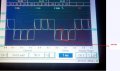
So I un-soldered the connection between the gates of T7 and T8, I then soldered a 220K resistor between the 2 and then I put one probe on the gate of T7 and one on the gate for T8 and this is what it displayed, channel 1 (yellow) was connected to T7 and Channel 2 is connected to T8.
I also attached the ground to T7 and a test probe to T8 and there was 11.5 volts present. Isn't that a bad thing?
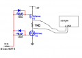
Indeed, it's strange. (220k is too big actually) Did you connected it like this?
Attachments
-
 13.1 KB Views: 39