Electro magnet project

praondevou

Joined Jul 9, 2011
2,942
That's how I understand it as well. to clarify then,I will set the scope to a certain time (say 50 us) probe the output of the 258 and when it get's to the 3 volts (where it oscillates) pause it and count the waves that are displayed on the screen? and by doing that, you will be able to take the 2 numbers and determine the frequency?
Yes.

So I un-soldered the connection between the gates of T7 and T8, I then soldered a 220K resistor between the 2 and then I put one probe on the gate of T7 and one on the gate for T8 and this is what it displayed, channel 1 (yellow) was connected to T7 and Channel 2 is connected to T8.

I also attached the ground to T7 and a test probe to T8 and there was 11.5 volts present. Isn't that a bad thing?

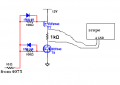
Indeed, it's strange. (220k is too big actually) Did you connected it like this?


Attachments

Thread Starter

JCOX

Joined Nov 29, 2011
136
With a big sigh...no,

This is how I set it up.


However, this morning I removed the diodes from the circuit and replaced the 220k with a 1k and the scope was flat lined at 0V.
 

praondevou

Joined Jul 9, 2011
2,942
However, this morning I removed the diodes from the circuit and replaced the 220k with a 1k and the scope was flat lined at 0V.
Ok, now you had it setup as per my previous post and the gates were both driven by the signal from the NOR gate and there was nothing to catch on the scope. Is that correct?

A possible pulse would occure for a very short time, so you'd need to choose a very short timebase for the scope...

I guess it will probably be ok though if you couldn't see anything.

If that is ok then you can move on to and do the other tests I recommended.
 

Thread Starter

JCOX

Joined Nov 29, 2011
136
Ok, now you had it setup as per my previous post and the gates were both driven by the signal from the NOR gate and there was nothing to catch on the scope. Is that correct?
Yes the scope was flat lined at 0v.

A possible pulse would occure for a very short time, so you'd need to choose a very short timebase for the scope...
I had it set at the shortest time possible, not even a slight hiccup in the wave

I guess it will probably be ok though if you couldn't see anything.

If that is ok then you can move on to and do the other tests I recommended.
will do
 

Thread Starter

JCOX

Joined Nov 29, 2011
136
Bad news, I soldered 4.7k resistors in place of the coils and had everything set up, had the ammeter in line and 4 probes set on the drains of each of the transistor sets, turned it on, the ammeter displayed 0.14A but the scope didn't display anything. I turned it off and rechecked all the connections, nothing was obvious. everything was connected properly. I disconnected the FET's from everything and tested the outputs from the 4017, the signals that were coming out of them was only displaying 2.2v and the lines on the scope wasn't as crisp either. I fear that I ruined it. the signal coming out of the 555 is still there (not as crisp either)

I went into trouble shooting mode and started running everything through my head and nothing.

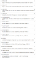
Can I get clarification on where the Gate, Drain and Source in this schematic? I labeled them in orange are they right:
 

praondevou

Joined Jul 9, 2011
2,942
Bad news, I soldered 4.7k resistors in place of the coils and had everything set up, had the ammeter in line and 4 probes set on the drains of each of the transistor sets, turned it on, the ammeter displayed 0.14A but the scope didn't display anything. I turned it off and rechecked all the connections, nothing was obvious. everything was connected properly. I disconnected the FET's from everything and tested the outputs from the 4017, the signals that were coming out of them was only displaying 2.2v and the lines on the scope wasn't as crisp either. I fear that I ruined it. the signal coming out of the 555 is still there (not as crisp either)

I went into trouble shooting mode and started running everything through my head and nothing.

Can I get clarification on where the Gate, Drain and Source in this schematic? I labeled them in orange are they right:
Yes the pinout of the FETs is correct.

All outputs of the 4017 have constant output of 2.2V? Or are they switching?

140mA looks like a lot to me...

Thinking...
 

praondevou

Joined Jul 9, 2011
2,942
Sorry yes it's switching from +12v to 0V.
Ok, so the outputs of the 4017 are switching from 12V to 0V. That means they are ok.

There is however one thing we need to check. This thread has become so big, I don't know anymore if you used the 4025 or the 4075.

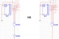
If it's the 4025 which is a NOR gate, the 3 inputs have to be connected to the first 3 outputs of the 4017. Sorry if I forgot to mention it . Nothing would burn but it just wouldn't work.

So if it's the 4075 then the inputs are connected to Q3 through Q5 of the 4017.
If it's the 4025 then the inputs are connected to Q0 through Q2. (or leave them connected to Q3 through Q5 and add a spare 4049 gate after the 4025, that's the same thing as having a 4075)
 

Thread Starter

JCOX

Joined Nov 29, 2011
136
It is the 4025, If I hook it up that way then everything should work properly?
That should be fairly easy. what about Q3-Q5? Do they still go into 4049?
 

Thread Starter

JCOX

Joined Nov 29, 2011
136
does it matter which wire goes into the 4025? other words does pin 2 of the 4017 have to go into pin 2 of the 4025? or can it go into pin 1 or pin 8?

edit: by the way I chose option 2.
 

praondevou

Joined Jul 9, 2011
2,942
Is the oscilloscope battery driven / does it have a battery charger like power adapter?

Is the power supply output isolated from the ground pin of the power cord?

Something to check just in case.
 
Last edited:

Thread Starter

JCOX

Joined Nov 29, 2011
136
I let it run for about 4 minutes and I felt the Fets for heat and T7/T8 were warm, all the others were cool to the touch.

Is the oscilloscope battery driven / does it have a battery charger like power adapter?

Is the power supply output isolated from the ground pin of the power cord?

Something to check just in case.
That is something I don't know, there is a battery for it but because when we use these scanners in the lab we have them plugged into 110v all the time so the batteries were removed and stored.
 
Last edited:

Thread Starter

JCOX

Joined Nov 29, 2011
136
Ok, here's an update, made it to where I only see 1 output at a time, I have the grounded probe of the scope connected to the drains of T7 and T8, the green lead is connected to T1/T2 drains, this is what I get:


Now the yellow lead is connected to T3/T4 and this one concerns me because it spikes in both directions, I'm pretty sure that's not normal, right? I'm assuming that it's because of the relationship of T7 and T8 and the slow on time and that's right when they are flip flopping...???


and here is T5/T6, it is what I would expect all of them to look like,


the current flow is consistent 150mA, I disconnected the power to the FETs circuit board and got 8mA and then plugged that board back in and disconnected the power to the logic portion and there was 1mA. so the high current is due to the operation of the FET's

Thoughts? comments?
 

praondevou

Joined Jul 9, 2011
2,942
I see almost 13 pulses per 1ms , is that correct? That corresponds to a 555 frequency of 13kHz.

Can you verify this? Measure with the oscilloscope at the output of the 555?

I don't know if T7/T8 getting warm and the 140mA are something to worry about. First we need to check that frequency.

Right now the rotor would turn once every 570μs, that's 1754 RPS.

Channel 2 showing these initial peaks could be due to the relative high load resistance you used (4k7) and the fact that at the moment the peaks occur the corresponding transistors were off, i.e. the voltage potential between is floating (actually tied to the drains of T7/T8 via the resistor itself).

It may not be something to worry about.

Try to lower the frequency to a few 10s of Hertz and test again, measure current as well (that was very useful information).

If nothing works I should have these transistors somewhere, so maybe I could test it...
 

praondevou

Joined Jul 9, 2011
2,942
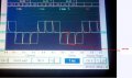
Can you do me a favor and zoom in here (still with the high frequency)?
Nothing to worry about but it looks as if it turns one coil on before it turns the other one off... That is actually not possible.


Attachments

Top