Facebook
 Google
 GitHub
 Linkedin
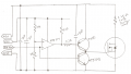
OK, so just suppose that the motor has 100A current flow (and nothing to sustain it), it has an inductance of 10H (I'm probably quite a bit low there) and your six 2uF caps in parallel with a super-duty diode to use to charge the caps with, then after about 20mS, you'd have ~91kv on the caps.I just bought 6 of these
1000v ; 2uf ; 400V/uSec ; 800A-peak ; 22A-ripple ; 7mΩ ESR
Oops, they're only rated for 1kv.
I see smoke and flames in your future.