Electric fly swatter dead

Thread Starter

Klaidas Stumbras

Joined Jul 7, 2016
19
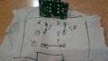
Trying to repair this thing the thing is it broke like a year ago and i dont really know where to put what so can anyone help me with this ?
Also there was this small resistor near it i dont know if it is from it or not ... ;D i have the missing transistor and light emiting diode but i dont know where to solder it ...
 

Attachments

wayneh

Joined Sep 9, 2010
17,498
why not when you have spare parts ? also its really hard to get those where i live
Why not? Because it will be nearly impossible without a schematic - which may be very hard to find - or another similar unit to copy.

How did the parts get separated in the first place? (Not that it matters, just curious how it came to be in pieces. )
 

absf

Joined Dec 29, 2010
1,968
I did some study on your PCB and this is what I came out with...

swatter pcb.jpg

The transistor can either sit on the blue line or in the black line. Is the 1K resistor on top right the one that came out?

Next you need to use an ohm meter to see continuity on the transformer. I think A-B is one coil and C-F another. What about D & E? Is there any continuity?

Allen
 

Thread Starter

Klaidas Stumbras

Joined Jul 7, 2016
19
Why not? Because it will be nearly impossible without a schematic - which may be very hard to find - or another similar unit to copy.

How did the parts get separated in the first place? (Not that it matters, just curious how it came to be in pieces. )
The transistor exploded thatsw why I desoldered the low voltage side
 

Thread Starter

Klaidas Stumbras

Joined Jul 7, 2016
19
I did some study on your PCB and this is what I came out with...

View attachment 108857

The transistor can either sit on the blue line or in the black line. Is the 1K resistor on top right the one that came out?

Next you need to use an ohm meter to see continuity on the transformer. I think A-B is one coil and C-F another. What about D & E? Is there any continuity?

Allen
Can't check the continuity as I m not at home .You got the V+ and 0v in terminals wrong way
 

Thread Starter

Klaidas Stumbras

Joined Jul 7, 2016
19
I did some study on your PCB and this is what I came out with...

View attachment 108857

The transistor can either sit on the blue line or in the black line. Is the 1K resistor on top right the one that came out?

Next you need to use an ohm meter to see continuity on the transformer. I think A-B is one coil and C-F another. What about D & E? Is there any continuity?

Allen
There is a resistor in that top right
 

Thread Starter

Klaidas Stumbras

Joined Jul 7, 2016
19
I did some study on your PCB and this is what I came out with...

View attachment 108857

The transistor can either sit on the blue line or in the black line. Is the 1K resistor on top right the one that came out?

Next you need to use an ohm meter to see continuity on the transformer. I think A-B is one coil and C-F another. What about D & E? Is there any continuity?

Allen
I could only find one coil resistance without desoldering the transformer coils tho are connected somewhat like this i think
 

Attachments

Top