Electret Microphone circuit design

GopherT

Joined Nov 23, 2012
8,009
Thank you guys again! I tried the Virtual Ground circuit and attached is the waveform for when I tap the microphone continuously after a two stage gain. first one 7x (turned the first voltage follower to provide a gain) and another one with 200x at end of filter. I see an output of 1.44Vpp but doesn't seem to pick up voice :/ Any Advice?
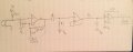
Remove C1. It is filtering your mic output.
 

GopherT

Joined Nov 23, 2012
8,009
The output swing of LM358 is 0V to 3.5V on a 5 volt supply. Set your virtual ground to 3.5V/2 = 1.75V.

Your output is clipping as of now. Also, don't over amplify - your total voltage (peak to peak) will be 3.5V.

upload_2017-1-30_16-8-52.png
 

ronv

Joined Nov 12, 2008
3,770
Thank you guys again! I tried the Virtual Ground circuit and attached is the waveform for when I tap the microphone continuously after a two stage gain. first one 7x (turned the first voltage follower to provide a gain) and another one with 200x at end of filter. I see an output of 1.44Vpp but doesn't seem to pick up voice :/ Any Advice?
Maybe a new schematic?
 

Thread Starter

soulhealer95

Joined Jan 17, 2017
9
The output swing of LM358 is 0V to 3.5V on a 5 volt supply. Set your virtual ground to 3.5V/2 = 1.75V.

Your output is clipping as of now. Also, don't over amplify - your total voltage (peak to peak) will be 3.5V.

View attachment 119658
Just to clarify, I'm using LMC660. And will upload a schematic asap. also by C1, you mean the coupling cap to Mic, right? the other one is supposed to be a filter. Will try removing it. Also, silly I know, but could someone please explain what we're trying to accomplish when we use a Virtual ground?
 

GopherT

Joined Nov 23, 2012
8,009
Just to clarify, I'm using LMC660. And will upload a schematic asap. also by C1, you mean the coupling cap to Mic, right? the other one is supposed to be a filter. Will try removing it. Also, silly I know, but could someone please explain what we're trying to accomplish when we use a Virtual ground?
A virtual ground sets An anchor in the center of the up and down swings of the voltage that make your audio-frequency waves.
 

Thread Starter

soulhealer95

Joined Jan 17, 2017
9
Apologize for the delay. Attached is the new circuit diagram. I figured out the problem in the circuit before (I didn't connect the Virtual ground correctly). Anyway, I fixed that issue and measured to confirm the voltage outputting at Vg is in-fact ~2.5Vdc.

But there is a new problem now. As soon as I connect my Virtual ground, apparently, all the op-amps just die. there is no output on any of them. I suspected I might have burned them or something but as soon as I connected the 10k resistor on the first amplification stage to real ground I saw an output indicating the opamps are fine (or atleast working). Any ideas what might be the issue?


Thank you all again!
 

Attachments

GopherT

Joined Nov 23, 2012
8,009
Apologize for the delay. Attached is the new circuit diagram. I figured out the problem in the circuit before (I didn't connect the Virtual ground correctly). Anyway, I fixed that issue and measured to confirm the voltage outputting at Vg is in-fact ~2.5Vdc.

But there is a new problem now. As soon as I connect my Virtual ground, apparently, all the op-amps just die. there is no output on any of them. I suspected I might have burned them or something but as soon as I connected the 10k resistor on the first amplification stage to real ground I saw an output indicating the opamps are fine (or atleast working). Any ideas what might be the issue?


Thank you all again!
Don't connect your mic directly to the op amp. Use a capacitor instead.

Also, label the capacitors and resistors.
 

Thread Starter

soulhealer95

Joined Jan 17, 2017
9
Don't connect your mic directly to the op amp. Use a capacitor instead.

Also, label the capacitors and resistors.
Thanks, Here's an updated diagram with labels. Now, If I add the Cmic to the circuit, the Ri forms a filter with the mic input resulting in disfigured output. I don't get why I need the Ri (which we concluded I did in previous posts)?
 

Attachments

GopherT

Joined Nov 23, 2012
8,009
Thanks, Here's an updated diagram with labels. Now, If I add the Cmic to the circuit, the Ri forms a filter with the mic input resulting in disfigured output. I don't get why I need the Ri (which we concluded I did in previous posts)?
The input (+) is very high resistance so charge gets caught between cap and input and signal will get lower and lower in the first seconds to minute as the amp saturates. It is wors for jfet inputs but still bad practice for bipolar input amps. That resistor can be 1M or so - the filter will be way out of audio range.

I meant that you should label the values of your cap and resistors. I don't want to read through all the notes to check values in the text.
 
Top