Facebook
 Google
 GitHub
 Linkedin
Hey everyone,
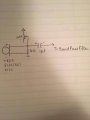
I'm trying to work with this electret microphone (http://www.digikey.ca/product-detail/en/pui-audio-inc/POM-3535L-3-LW100-R/668-1496-ND/5414026), but it just wont work. I'm certain it must be something silly I can't see. Anyway, attached is the circuit. Vcc is 12V.
Here's what I have tried:
- Using a voltage divider
- Varying the Cap values
- Varying Vcc (5-10V)
- Using different Resister values
- Using different Microphones
- Amplification to up to 100 gain (using LM741 and LM348n)
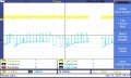
I have tried using a scope right at the base of the microphone, when I tap it, there is very, very, subtle pulse but that doesn't happen always and no voice goes through at all (apparently). I have been trying to troubleshoot for four days now.
Please help me see the little bug. Tips for troubleshooting. Things to try. ANYTHING would help. Thanks!")
I'm trying to work with this electret microphone (http://www.digikey.ca/product-detail/en/pui-audio-inc/POM-3535L-3-LW100-R/668-1496-ND/5414026), but it just wont work. I'm certain it must be something silly I can't see. Anyway, attached is the circuit. Vcc is 12V.
Here's what I have tried:
- Using a voltage divider
- Varying the Cap values
- Varying Vcc (5-10V)
- Using different Resister values
- Using different Microphones
- Amplification to up to 100 gain (using LM741 and LM348n)
I have tried using a scope right at the base of the microphone, when I tap it, there is very, very, subtle pulse but that doesn't happen always and no voice goes through at all (apparently). I have been trying to troubleshoot for four days now.
Please help me see the little bug. Tips for troubleshooting. Things to try. ANYTHING would help. Thanks!
Attachments
-
 33.7 KB Views: 57