 Facebook
 Google
 GitHub
 Linkedin
Hi,
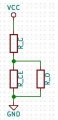
I'm trying to go through the very basics using the Talking electronics book. Chapter 8 discusses transistors and the performance of various amplifiers. It says that the effective load is R_C // R_O and since R_O is much larger this reduces to R_C (see first attachment). But how do you arrive at R_C // R_O?
Suppose we replace the collector emitter junction with a resistor R_CE (second attachment), I would understand that the load is R_C + R_CE // R_O. Since R_CE << R_O this would reduce to R_C + R_CE. Perhaps R_CE << R_C so you would arrive at R_C too. But that's not what the book says.
Can you help me understand this?
Attachments
-
 60.3 KB Views: 8
 -
 11.4 KB Views: 4


