Tom66,
Ok I will re-check all the solder joints.
In the meantime can you tell me what you would expect to see as an expected input signal voltage and output signal voltage "on the bench" with a baseline voltage of approx 10V?
Tom66,
Ok I will re-check all the solder joints.
In the meantime can you tell me what you would expect to see as an expected input signal voltage and output signal voltage "on the bench" with a baseline voltage of approx 10V?
Im having a stupid moment, Maybe I should clarify, what I am asking is on the bench: no speedometer in circuit and no ECU in circuit.
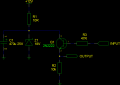
Following the schematic: If I give the board a supply voltage of 10V (simulating IGN power and a ground) what can I expect to see at the output line to the speedo and at the input line from the ECU.
Approx the same voltages (given the line from the ECU has a 10K resistor)?
Im having a stupid moment, Maybe I should clarify, what I am asking is on the bench: no speedometer in circuit and no ECU in circuit.
Following the schematic: If I give the board a supply voltage of 10V (simulating IGN power and a ground) what can I expect to see at the output line to the speedo and at the input line from the ECU.
Approx the same voltages (given the line from the ECU has a 10K resistor)?
Indeterminate - you need to have it connected to something or it could well pick up atmospheric noise (e.g. a local radio station.) Sounds crazy but it can happen, especially with CMOS/FET op-amps.
So if I'm getting this straight, you are still getting the error code with the speedo connected? Where is the error code coming up on, the ECU or the speedo?
With the op amp connected (as per last test config) there is no error code from the ECU. Problem is the speedo always reads 0 kph. The speedo will work when the op amp is out of circuit, however the ECU finds a fault which is displayed on the ECU itself.
I cannot bypass the ECU to remove the VSS signal and only feed the speedo as the engine will not operate properly without a VSS signal.
With the op amp connected (as per last test config) there is no error code from the ECU. Problem is the speedo always reads 0 kph. The speedo will work when the op amp is out of circuit, however the ECU finds a fault which is displayed on the ECU itself.
I cannot bypass the ECU to remove the VSS signal and only feed the speedo as the engine will not operate properly without a VSS signal.
So how do you know the speedo is even working without an engine to test the speed?
It's possible that the signal is a very fast PWM signal and the op-amp isn't fast enough to buffer this. In which case we will need to go back to the drawing board, I will have a circuit up which should be able to do what you want in an hour or so.
I am driving the car when I test with or without the amp.
The car will run with the ECU code, only the ECU defaults to "LIMP HOME" mode when this code is logged. The effect is noticeable (to me anyway) minimal fuelling/fixed advance curves. It is basically a protection mode for the engine.
You will only need another device, Q1, a 2N2222 transistor, as well as one additional resistor, a 10k (I tried to keep the other resistors the same.) The transistor can also be replaced with a 2N3904 or BC547
Tom66
Many thanks for your continued assistance, how did you come up with this new circuit so fast!
I cant find any written references to this being an actual PWM signal from the VSS however it may well be. Nevertheless, will this new circuit still work if the signal is not a PWM as it is simply seeing a pulsed voltage?
Given my wheel circumference the VSS will generate around 4000PPM (pulse per mile).
Tom66
Many thanks for your continued assistance, how did you come up with this new circuit so fast!
I cant find any written references to this being an actual PWM signal from the VSS however it may well be. Nevertheless, will this new circuit still work if the signal is not a PWM as it is simply seeing a pulsed voltage?
Given my wheel circumference the VSS will generate around 4000PPM (pulse per mile).
It's a really basic circuit - took 5 minutes to draw up.
The problem with the original circuit might be that the op-amp does not have a high enough bandwidth or slew rate to react to the pulses, i.e. they rise and fall too quickly for the output to change. It could be smoothing out the pulses causing the ECU or speedo to discard them.
The transistor is simply used as a switch in this configuration; it does not buffer the signal. The VSS is likely a PWM signal as it detects the rotations of the wheel. This is then sent to the ECU which samples the signal to determine the frequency.
A single transistor like this has 100x as much bandwidth as the op-amp.
tom66
Built the hi speed circuit today and tested on car, no VSS fault however speedo still reads 0.
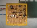
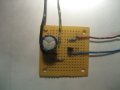
Pics of board attached can you please see if i wired it correctly, the zener is not quite visible its below the cap
I've reviewed the circuit you built and can't see a fault.
Hmm.
Can you try connecting the input of the circuit to the 12V source. The output should go high (almost 12V.) Then disconnect it - it should go low (almost 0V.)
Is there any chance of you borrowing a scope? The signal could be more complex than we think (maybe it's bi-level, or very fast) and these circuits can't buffer the signal sufficiently.
Tom 66 Tried the 12v/0v test as you suggested, and the circuit performs exactly as you said it would. Now for more recent developments. Started looking to borrow a scope from a friend, who put me in touch with a contact of his who installs electronic taximeters, yes that right a taximeter. After some conversation with him on my problem, he explained that the VSS output is a Square wave and in his experience usually only provides sufficient output to drive the ECU. Anything else tapped into the circuit will generally not work properly unless the signal is boosted. In his business he uses a VSS Divider which according to him did not affect the original VSS signal to the ECU. This unit is normally installed between the taximeter and the ECU. I found that the company who manufactures this device is a local one to me. So I paid a visit to their engineering dept for more info. The eng. told me that this VSS divider does exactly what we have been attempting to do. Provides a buffer between the ECU and whatever else the signal is running to, increases the signal pulse via an amp and additionally can be adjusted to meet the PPM/K needs of the unit it is driving. For me the latter part is not needed as my speedo can be calibrated to read pulses between 1000 to 40000.
Needless to say I had to try it out, and at $40.00 Cdn it was worth a shot. Upshot is, it worked. Speedo reads and no VSS faults.
I almost feel cheated having found a ready made solution so close at hand and would have really liked to have built the answer to this problem. I also believe that you were following the right track and would have come to the same results being offered by the manufacturer of this device.
Nevertheless, regardless of the outcome, I really appreciate the time you and the rest of the members on this site have given to me. Additionally my own comprehension on circuits in general has improved considerably from your guidance and I will endeavor to continue this learning experience by more regular visits to this site.

 Facebook
 Google
 GitHub
 Linkedin