ECG Help, LM 741 1 OP AMP Circuit

Thread Starter

giovannelucas_

Joined Jan 5, 2023
39
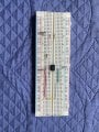
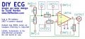
Hi everyone, I'm trying to build a version of an open-source ECG project that uses a LM741 as the OP AMP to amplify the ECG signal and send it to serial monitor on the arduino IDE in order to read the graphic.

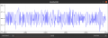
However, I'm not able to see a proper ECG plot, however I see a different random plot.

Below is my circuit and the proposed schematic as well as the plot I'm getting on the arduino IDE.

Thank you for reading.

All help is welcome.
 

Attachments

DickCappels

Joined Aug 21, 2008
10,659
You need a really low noise opamp with a carefully laid out circuit. Those general purpose opamps from the 1970's aren't going to make it.

You might find this useful. Note the amplifiers being used and how they are connected. As Bertus mentioned, you need to keep the construction tight to avoid picking up noise

https://www.egr.msu.edu/classes/ece...ocuments/ElectrocardiographyCircuitDesign.pdf

Read about other ECG circuits and notice the construction techniques.
 

Thread Starter

giovannelucas_

Joined Jan 5, 2023
39
Hi @bertus and @DickCappels , I made two schematics based on the tips you gave me. Including changing the OPAMPS to something better. I chose the OPA333 and INA333 as they were in a circuit shown in the pdf file bertus attached to the response.

The second schematic has a patient protection and isolation circuit. Does it look alright?
How does the layout of the board influence the performance of the system? I had a lot of problems with made at home boards before. Is there such a thing as magnetic field interference created on other tracks as currents travels through it?

Another doubt is how to test these schematics before sending them off to production? As they are SMD, it is not possible to test them on a breadboard, plus it is a complex circuit.

Would manufacturing the board the only way to test it?

I have two headphone jacks, one for input with the electrodes and another for output. Are they acceptable?
I think of changing input to a standard ECG cable and output to serial usb communication as with the arduino. Would I need to use an ATMEGA or STM32 for that?

I am attaching the schematics below.

Thank you for the response.
 

Attachments

seanstevens

Joined Sep 22, 2009
323
Just a quick check of your circuit vs your breadboard shows your R5 is not connected, instead, you have wires looping between pins 2 and 6 that's no gain.
Also as mentioned by others, you need a good opamp for this kind of circuit. Just remember, you MUST NOT EVER use this circuit with a mains adapter, it can only be used with a battery unless you want to kill whoever is connected to it!
 

Thread Starter

giovannelucas_

Joined Jan 5, 2023
39
Just a quick check of your circuit vs your breadboard shows your R5 is not connected, instead, you have wires looping between pins 2 and 6 that's no gain.
Also as mentioned by others, you need a good opamp for this kind of circuit. Just remember, you MUST NOT EVER use this circuit with a mains adapter, it can only be used with a battery unless you want to kill whoever is connected to it!
Hi Sean, sure I’m not powering it from the mains.
 

schmitt trigger

Joined Jul 12, 2010
2,107
Many years ago, I was part of an engineering team which designed and built a commercial ECG monitor.
Without spilling the beans too much, all I can tell you is that you must use the instrumentation amplifier configuration. Please Google the term.
Apart from starting with a precision low offset opamp, the resistor network should be matched to no less than 0.1% for optimal CMRR. Otherwise, environmental noise will swamp your signal. This is a tall order, fortunately Texas Instruments and Analog Devices offer monolithic IC instrumentation amplifiers.

How important is this CM rejection? A true story will illustrate this: As I was testing a prototype in the lab, periodically but at random times I would get a noise burst. Struggled to find the cause for hours, until I noticed from the corner of my eye that when a laboratory technician, standing perhaps 10 feet away, would move, the noise would be recorded. Turns out that it was a cold winter and the technician was wearing a 100% pure wool sweater. The wool’s tribioelectric effect would radiate the electrical noise!!
 
Last edited:
Top