EC11 Rotary encoder quiery

Thread Starter

cce427

Joined Jun 30, 2022
2
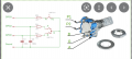
I am a retired electronics engineer and make things I sell on Fleebay and Amazon using EC11 rotary encoders after many years with the same supplier I bought some elseware and they work in an oposite rotation, I am baffled, how ? anyway I need to build something to test the rotation direction so I can wire them correctly in my device, any ideas ?

Chris
 

ericgibbs

Joined Jan 29, 2010
18,874
hi Chris,
Welcome to AAC.
I have a set-up using a ESP32 that gives an output sense depending upon the shaft rotation direction.
Are you familiar with MCU modules.?
E
 

Thread Starter

cce427

Joined Jun 30, 2022
2
hi Chris,
Welcome to AAC.
I have a set-up using a ESP32 that gives an output sense depending upon the shaft rotation direction.
Are you familiar with MCU modules.?
E
Hi I know what an MCU module is but that is it, sounds an expensive solution ?
 

ericgibbs

Joined Jan 29, 2010
18,874
hi Chris,
Just made up a simple test jig, two LED's and 1k Resistor, the LED's indicate which section of the EC11 switch makes first, so that you can determine direction.
I will post a sketch.
E

Ref image.
The Three contact legs of the EC11.
Left to D1, Right to D2 and the resistor to the centre pin,
Slow turn CW or CCW lights the contacted LED.
Do you follow, OK.?
 

Attachments

Last edited:

MisterBill2

Joined Jan 23, 2018
18,600
If you can work with an IC, use a CD4027 JK flipflop and start with one of the encoders you know, connect one phase to the "Clk" pin and the other output to the "J" pin. You will also need to connect LEDs to the Q and Qnot outputs. In one direction the "Q" output will light and in the other direction it should not light. You will need to assure starting with the FF reset (Qnot on). Since you already have the power supply, this system might cost $2.
 

ericgibbs

Joined Jan 29, 2010
18,874
Hi,
No logic is required, just two LED's and one resistor, its that simple.

Absolutely no point in over complicating the test jig.

E
 

ericgibbs

Joined Jan 29, 2010
18,874
Hi,
I have a working set up on the bench, it is not a problem determining which comes first A or B phase depending on the direction of stepping the encoder shaft.

The TS already regularly uses the original version, so by testing one of those the direction is determined, so when he gets future deliveries of the EC11 he can check the A/B sense.

Why do you always want to undermine, to the TS, the posts put forward by other members, thus leaving doubt in the TS mind???

E

Added image of the EC11.
 

Attachments

Last edited:

MisterBill2

Joined Jan 23, 2018
18,600
Hi,
I have a working set up on the bench, it is not a problem determining which comes first A or B phase depending on the direction of stepping the encoder shaft.

The TS already regularly uses the original version, so by testing one of those the direction is determined, so when he gets future deliveries of the EC11 he can check the A/B sense.

Why do you always want to undermine, to the TS, the posts put forward by other members, thus leaving doubt in the TS mind???

E
My intention was never undermining as you put it. It seems that determining which phase is leading needed a bit more than justseeing the LEDs alternately illuminate. I did not know that the TS had some physical setup already in place, That makes a bit of difference. And my original idea was to have an up/down counter to do the evaluation. But I could not recall the device that was used for that and so I suggested an alternative. I am off this thread.
 
Top