Console for starting up a rotary phase converter

Thread Starter

jorgewad

Joined Oct 15, 2024
8
I am building this.
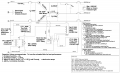
I am currently struggling figuring out how is the wiring for the SSR and the Cstart capacitor, it is supposed to enter the circuit when the 24v dc coil of the SSR is energized, the Cstart capacitor is connected between the two lines of the idler motor,. The diagram shows the SSR connected to timer relay. The video of this project shows the Cstart capacitor connected directly to the SSR then to one line of the contactor, the other terminal of the SSR also connected to other line od the contactor. I am confused, I think I am interpreting the diagram wrong for the SSR connections and Cstart capacitor.


Attachments

MaxHeadRoom

Joined Jul 18, 2013
30,557
RPC are not as popular as they once were, now with the advent of VFD's.
I originally built one for my shop, before going VFD, but the start sequence is fairly simple.
 

panic mode

Joined Oct 10, 2011
4,864
that drawing has mistakes. TR-1 is a transformer, not a DC power supply. so secondary side is going to be AC and not DC. and therefore relays that are powered by it need coils rated for 24VAC, not 24VDC...
also the terminals/wires are not to be marked as is (24V+, 24V-, 24V DC Pos, 24V DC Neg).

or...

replace TR-1 with a 24VDC power supply...
 

panic mode

Joined Oct 10, 2011
4,864
also i would not switch CT-1 coil on the neutral side, contact of REL-1 should be on the line side of that coil.
the SW-1 mushroom switch should be normally closed (pulled out = closed, pressed = open).
the circuit breaker symbols represent contacts of contactors...
the BOM does state that TR-1 is 120VAC / 24VDC "transformer" (should be called power supply and represented in circuit as such).
 
Last edited:

panic mode

Joined Oct 10, 2011
4,864
I am confused, I think I am interpreting the diagram wrong for the SSR connections and Cstart capacitor.
what is that you find confusing? start capacitor is connected on startup only, then it is turned off. adding capacitor create phase shift needed to simulate missing 3rd phase and allow motor to start rotating. once it runs, this is removed. that is why timer is there.
 

Thread Starter

jorgewad

Joined Oct 15, 2024
8
that drawing has mistakes. TR-1 is a transformer, not a DC power supply. so secondary side is going to be AC and not DC. and therefore relays that are powered by it need coils rated for 24VAC, not 24VDC...
also the terminals/wires are not to be marked as is (24V+, 24V-, 24V DC Pos, 24V DC Neg).

or...

replace TR-1 with a 24VDC power supply...
I am using a dc power supply
 

Thread Starter

jorgewad

Joined Oct 15, 2024
8
what is that you find confusing? start capacitor is connected on startup only, then it is turned off. adding capacitor create phase shift needed to simulate missing 3rd phase and allow motor to start rotating. once it runs, this is removed. that is why timer is there.
Why in the diagram it shows ssr ac terminals connected to timer relay and in the video it clearly show the start capacitor in circuit with the ssr and the two lines of the contactor?
 

panic mode

Joined Oct 10, 2011
4,864
i do not have time to watch videos. you may post a link with exact time stamp. but schematics, while flawed, is usable.
SSR AC terminals connect to capacitor and L1. DC side terminals (aka "coil") connects to timer.

if you want someone to check the video out, post link with correct time so that clicking on link takes you to right moment in the video.,

when unit is started, timer turns starts timing. during that initial time SSR relay is on while CT-2 is deenergized. During this short startup time:
SSR os connecting starting capacitor to motor, producing fake third phase and allowing it to start running.
At the same time CT-2 is turned off so that any connected load is ignored. Because load would make starting very hard or impossible.

After startup time is done and when motor is turning, timer relay is done and changes state of the contacts, from this point on, startup capacitor is disconnected (because SSR is off) and load is connected (CT-2 is on).
At this point 3rd leg of the motor is not receiving power (to start turning), it is used to deliver power to load.

i rearranged couple of things, maybe this helps:
1729171452737.png
typical SSR wiring

1729172485705.png
 
Last edited:

Thread Starter

jorgewad

Joined Oct 15, 2024
8
i do not have time to watch videos. you may post a link with exact time stamp. but schematics, while flawed, is usable.
SSR AC terminals connect to capacitor and L1. DC side terminals (aka "coil") connects to timer.

if you want someone to check the video out, post link with correct time so that clicking on link takes you to right moment in the video.,

when unit is started, timer turns starts timing. during that initial time SSR relay is on while CT-2 is deenergized. During this short startup time:
SSR os connecting starting capacitor to motor, producing fake third phase and allowing it to start running.
At the same time CT-2 is turned off so that any connected load is ignored. Because load would make starting very hard or impossible.

After startup time is done and when motor is turning, timer relay is done and changes state of the contacts, from this point on, startup capacitor is disconnected (because SSR is off) and load is connected (CT-2 is on).
At this point 3rd leg of the motor is not receiving power (to start turning), it is used to deliver power to load.

i rearranged couple of things, maybe this helps:
View attachment 333820
typical SSR wiring

View attachment 333822
Thank you very much sir. I just understood everything with your rearrange of the diagram. All the fuss was because I was interpreting the line next to the 24v line coil of the ssr as the ac terminals of the ssr. Do yep. Thank you very much
 

MisterBill2

Joined Jan 23, 2018
27,164
I do not choose to watch most of the videos because it is many times a challenge to understand the speaking, which often seems to be in a real hurry. And if their thoughts are not organized enough to put into text then I am not interested. Besides that, it is way too easy to fake a video presentation.
 

panic mode

Joined Oct 10, 2011
4,864
videos are time consuming, one can read a text paragraph in seconds and skip through unnecessary details. but the same takes much more time and effort when reviewing videos which also tend to be peppered with ads. i am glad to offer help but don't have time to waste.

people asking for help need to do some legwork and present their case clearly and concisely so that one offering help is not wasting time...
 
Last edited:

MisterBill2

Joined Jan 23, 2018
27,164
In addition, I can slow down when reading a text, while in a video just backing up a bit is often tedious. On top of that not all of the talkers in a video speak to be understood. Not a big problem with reading text.
 
Top