Dusk to dawn switch using low voltage ac with ac output

Thread Starter

punkieys17

Joined Oct 4, 2014
18
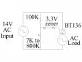
The garden pump had a LED ring light around it with a separate transformer supplying 14V AC which passed through a LDR switch then onto the LED ring. While I can find very simple 230V triac based circuits I'automatic-night-lamp-circuit-230v.gifm struggling to find one for such low AC voltages. I have attached an example of such a 230V AC. Can I modify this to work...my calculations suggested that a 1n4001 diode and a 270K pot would be OK. Any thoughts greatly appreciated. Julian
 

LesJones

Joined Jan 8, 2017
4,174
LEDs run on DC so there is probably a rectifier between the AC input and the actual LEDs. It is just possible that there pairs of LEDs are connected with reversed polarity so one lights on the positive half of the cycle and the other one lights on the negative part of the cycle. I suggest investigating exactly how the LEDs are fed from the 14 volt AC supply. As the circuit in your post uses an SCR it will only conduct on half of the cycle. If you replaced the SCR with a triac and removed the diode it should work. The value of the resistor will also depend on the type of LDR that you use.'

Les.
 

ci139

Joined Jul 11, 2016
1,898
the LDR should be temperature compensated UV Light IR Heat - all the same thing at significant amounts
 

Thread Starter

punkieys17

Joined Oct 4, 2014
18
Hi guys, many thanks for the reply. The light ring (just like the sensor) is encapsulated so impossible to see anything. I checked the Ac transformer output and that links to the sensor. Both transformer and sensor have a connector with no polarity so was happy to just connect the transformer to the LED ring - which lit up correctly. So just doing some investigation on what triacs I have in the bottom of the tool box....an somewhere I have a ORP12 from memory - though I see 5mm LDRs are really cheap on ebay.
 

Thread Starter

punkieys17

Joined Oct 4, 2014
18
So found a BT136 triac and a LDR with 100mW max power and resistance 20k to 1M. Think a 1M resistor would work fine as the gate voltage is 1.5V. Can anyone please explain the use of the diac and if it will still work on the 14AC power. streetlight.jpg
 

Dodgydave

Joined Jun 22, 2012
11,285
The Diac works on 27V, as stated put two zeners back to back instead.

You can still use your Thyristor circuit if you puta Bridge rectifier on the input AC, then connect the thyristor circuit.

SCR-basic.gif
 
Last edited:

Thread Starter

punkieys17

Joined Oct 4, 2014
18
So found a BT136 triac and a LDR with 100mW max power and resistance 20k to 1M. Think a 1M resistor would work fine as the gate voltage is 1.5V. Can anyone please explain the use of the diac and if it will still work on the 14AC power. View attachment 193734
Hi Ci139. Think I understand - you mean 2 zeners side by side with one pointing oe way and one pointing the other. Diacs only seem to be commonly available with 30V pluis - so couldn't use one anyway with a low AC supply voltage. About to put it together so will let you know...Many thanks to all for the help.
 

Thread Starter

punkieys17

Joined Oct 4, 2014
18
Hi DoggyDave. OK sorry I misunderstood. So you are talking about the arrangement "b" in the attached file - not "a". Also the LDR appears to vary between 3k and 800k - so instead of the 1m I had thought I will drop it down to 100k. This will give a voltage to the back to back zeners that in light conditions sits at 13.6V and in dark down at 1.5V. Actually thinking about it doesn't that mean it will be on when light and off when dark...Suspect I need to swap the position of the LDR and resister... dont I?
 

Attachments

Thread Starter

punkieys17

Joined Oct 4, 2014
18
bertus - I hear what you are saying re the zeners...but any idea how it can be achieved. The circuit I removed had very few components with no rectification to create a DC circuit. Anyway the output is an AC output. This is what I have so far...have swapped the LDR and resistor so it should now illuminate when dark falls.
 

Attachments

Dodgydave

Joined Jun 22, 2012
11,285
bertus - I hear what you are saying re the zeners...but any idea how it can be achieved. The circuit I removed had very few components with no rectification to create a DC circuit. Anyway the output is an AC output. This is what I have so far...have swapped the LDR and resistor so it should now illuminate when dark falls.
Yes you can use zeners back to back of you don't have any Diacs, this is light dimming, your circuit wiill be conducting the Triac at 4.7V On, you need to ring make sure the Zeners and Ldr are connected across the G and MT1 Terminals, so when darkness falls the Gate will fire the triac through the 100K resistor,
 
Last edited:

Thread Starter

punkieys17

Joined Oct 4, 2014
18
Gentlemen - success. Many thanks for all your help. With a few recalculations, discovering after a frustrating afternoon that I had managed to break a copper track on the the verostrip board, the circuit is working. I have included it just in case anyone else needs a low Ac voltage dusk to dawn circuit. Light1.jpg
 
Top