Dummy Load Design Feedback

Thread Starter

devonullo

Joined Feb 27, 2021
4
Hi there,

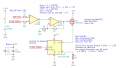
I'm trying to design a dummy load inspired by this project by GreatScott and using components I have on hand. I'm rather new to op-amp/mosfet based designs so I was wondering if there's anything wrong with the approach I'm taking. I've included my math and other notes I think were important for the design. One thing I was confused about was the max current source/sink on Iout of the ACS712 current sensor, I figured that was for the VIOUT pin, but I didn't fully understand why it would ever source current if its an output?


dummy_load_schematic.png
 

Attachments

LowQCab

Joined Nov 6, 2012
4,071
Most Sensors / Amplifiers both Source and Sink a specified maximum Current,
If you force them to supply more than that Current, the output Voltage will drop.

There are simpler Circuits than this.
This Circuit oscillates a some uncontrolled rate,
probably something that You don't want.

I don't see how this Feedback arrangement would be all that much more
accurate than just measuring the Voltage across the Resistor.
The Current Sensor is not much more accurate, if at all.

How much accuracy do You require ?
.
.
.
 

Audioguru again

Joined Oct 21, 2019
6,691
We do not know the actual, typical or minimum output voltages of the AC5712 or of the DAC and since the max voltages are so close together then many times the DAC signal is not higher than the AC5712 voltage and causes the circuit not to work.

The first opamp has a voltage gain of at least 25 thousand times so why is the second opamp used and is making the total gain 166 thousand times?
 

Thread Starter

devonullo

Joined Feb 27, 2021
4
Most Sensors / Amplifiers both Source and Sink a specified maximum Current,
If you force them to supply more than that Current, the output Voltage will drop.
Oh I think I understand now - the name given on the datasheet, Iout(source), is just a misleading name that refers to the amount of current the entire sensor sources. Thank you for explaining that.

There are simpler Circuits than this.
This Circuit oscillates a some uncontrolled rate,
probably something that You don't want.
I'm looking to test a power supply with a constant load or very slow switching load (3Khz max), and I've read LM358s are pretty slow so I was thinking it would be alright (maybe not, I have 0 experience with op-amps). I'm all about making this project simpler so if there's a better design I'd definitely like to see it! I was just following something I found online and using the parts I had on hand.

How much accuracy do You require ?
Well, I think tens of milliamps would be enough, but milliamps would be ideal. How could I work towards better accuracy?

Thanks for all your input, I appreciate your help.
 

Thread Starter

devonullo

Joined Feb 27, 2021
4
We do not know the actual, typical or minimum output voltages of the AC5712 or of the DAC and since the max voltages are so close together then many times the DAC signal is not higher than the AC5712 voltage and causes the circuit not to work.
Sorry, I should've included those:
ACS712: 2.5V to 3.425V
DAC is anywhere from (0 to 3.3V)
I'm not sure what the typical voltages would be... My guess would be if I'm using it for a 12V supply with 3A load, then maybe 4-5V on the output stage...

The first opamp has a voltage gain of at least 25 thousand times so why is the second opamp used and is making the total gain 166 thousand times?
... which makes me realize why I don't need the second op-amp :'D I was thinking that the output of the op-amp would be limited to the 3.3V of the DAC/ACS712... now I get it, I think!

Thanks for your help!
 

LowQCab

Joined Nov 6, 2012
4,071
The only inaccuracy in the following Circuit is the very small change
in Resistance of the Current-Sensing Resistor that occurs
because of the increasing Temperature of the Resistor.
A high-Quality, very over-rated, Current-Sense-Resistor will be quite accurate.
Its Resistance Value needs to be adjusted to suit the range
of Current that You need to use it for.
.
.
.
Voltage Controlled Current Sink FLAT .png
 
Top