 Facebook
 Google
 GitHub
 Linkedin
Hey guys,
I'm working on a GSM project using the SIM900A module, and yeah I <Mod: Obsecenity deleted> I totally forgot that SIM900A needs max 4.5V on the VBAT pin.
So I went ahead and designed my whole circuit thinking everything is 5V powered, including SIM900A.
Luckily, I had already added a diode for reverse voltage protection between USB power and external 5V (HLK-10M05L) input. And by pure luck, this diode has around 0.5V forward drop at 3A, so now my SIM900 is getting around 4.5V max.
I know this ain't the most professional way to regulate voltage but I'm not going for long-term use — just want it to work reliably enough to send some data via GSM.
My Questions:
Will this diode drop hack work fine for powering SIM900A short-term?
Do I need to add a 470uF cap close to VBAT pin or is it overkill?
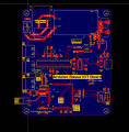
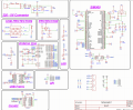
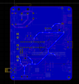
Could someone check my schematic (attached) and let me know if I missed anything else stupid?
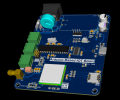
I’m using an SK36 3A 60V Schottky diode and have a P-MOSFET (DMG3415UFY4Q) to auto switch between USB and HLK-10M05L power.
I attached the schematic here
Thanks in advance any feedback, roast or tips welcome.
I'm working on a GSM project using the SIM900A module, and yeah I <Mod: Obsecenity deleted> I totally forgot that SIM900A needs max 4.5V on the VBAT pin.
So I went ahead and designed my whole circuit thinking everything is 5V powered, including SIM900A.
Luckily, I had already added a diode for reverse voltage protection between USB power and external 5V (HLK-10M05L) input. And by pure luck, this diode has around 0.5V forward drop at 3A, so now my SIM900 is getting around 4.5V max.
I know this ain't the most professional way to regulate voltage but I'm not going for long-term use — just want it to work reliably enough to send some data via GSM.
My Questions:
Will this diode drop hack work fine for powering SIM900A short-term?
Do I need to add a 470uF cap close to VBAT pin or is it overkill?
Could someone check my schematic (attached) and let me know if I missed anything else stupid?
I’m using an SK36 3A 60V Schottky diode and have a P-MOSFET (DMG3415UFY4Q) to auto switch between USB and HLK-10M05L power.
I attached the schematic here
Thanks in advance any feedback, roast or tips welcome.
Attachments
-
 234.6 KB Views: 1
 -
 335 KB Views: 2
 -
 220.4 KB Views: 1
 -
 284.3 KB Views: 0
Last edited by a moderator:


