 Facebook
 Google
 GitHub
 Linkedin
Somewhat new to all this DC electronics, but I try to research alot and learn. But I have one issue with a module for my motorcykle i can't figure out.
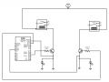
I'm trying to start the bike trough my ESP32/Arduino board. two connections and relays, one is power to the bike and fulepump etc that needs power all the time, the other is the ignition that just needs power at the start, so I have to split it up.
Both have 150mA at start and then down to around 40mA, with 12v.
If i connect one circit to ether the power circuit/relay or to the ignition circuit/relay it works fine.
But as soon as I connect both of them (as the diagram) at the same time all hell breaks loose. Ether nothing works, or the bike starts right away or only the ignition works etc etc. Everything but correct. It feels like the ground to the Arduino/ESP32 is the issue, but I dont know how to solve it any other way.
I start to get crazy with this now and have searched for days, but I cant find a simular problem. Please have understanding with my bad diagram but I try as good as I can.
Attachments
-
 27.6 KB Views: 11


