 Facebook
 Google
 GitHub
 Linkedin
Hi All
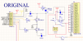
I made a Transistor switching circuit awhile ago for my car and it seemed to have worked (Attached as 'Original') . The idea was to allow two separate constant triggers (not at the same time), control ONE relay. The relay would turn on other 12V equipment in my car. The 12V input trigger seems to work while, but the Ground trigger is hit or miss. Mostly misses.
So I came up with a with the other attached circuit (Modified 1) to have the PNP drive the NPN for the Ground Trigger and it worked. .. But now the 12V input doesn't work anymore. The one thing that did work.
So now I'm thinking, maybe to use a P-CH mosfet in place of the PNP in the Original drawing, but use a 10K pull-up resistor on the gate.
Any input would be much appreciated.
Thank you
TONY
Attachments
-
 39.6 KB Views: 25
 -
 42.9 KB Views: 23


