In post number 12, the 3rd schematic down he shows a dual transistor driver for each output. You would add the relay where the two output transisors meet and ground.
The H-Bridge would then be constructed using the NC and NO contacts of the relay.
The concern I have is for the reversal period, over double the normal current could be produced when driving current in to reverse motor while it is still spinning in the "wrong" direction. Normally, both motors are connected to ground (or held open) for "Brake" for a moment, then the reverse voltage is applied.
Actually the drivers would handle it themselves, since they can go up to an amp with the right resistors.
Wookie has posted something very similar in the past, using relays as a crude H controller.
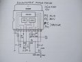
Lifting a stock image from my library the OP needs something like this...
This is not meant to replace what I've already drawn, it is to illustrate how it would be done.
I'll PM wookie and see if he can post his circuit up here. Between the 3 drawing there will be a complete schematic.
Besides the capacitors show (C2) you will need power supply capacitors that are not shown. Think 0.1µF and 220µF. The 5V can still be used for the 556 (or you can use 12V), but the relay and transistor will probably need the 12V (or whatever, depends on the relay voltage).
Actually the drivers would handle it themselves, since they can go up to an amp with the right resistors.
Wookie has posted something very similar in the past, using relays as a crude H controller.
Lifting a stock image from my library the OP needs something like this...
This is not meant to replace what I've already drawn, it is to illustrate how it would be done.
I'll PM wookie and see if he can post his circuit up here. Between the 3 drawing there will be a complete schematic.
Besides the capacitors show (C2) you will need power supply capacitors that are not shown. Think 0.1µF and 220µF. The 5V can still be used for the 556 (or you can use 12V), but the relay and transistor will probably need the 12V (or whatever, depends on the relay voltage).
Just theory, but I've made plenty of timers, and I've powered a lot of relays. It would work. The OP has updated the specs for the motor though, so some redesign is required.
OK, this will work, and CR1-4 are optional, but there is still a serious flaw in the concept. I don't think you (the OP) is prepared for the extreme currents you will get when the motor reverses direction. It may be a 1A motor, but it will pull a lot more than 1A doing this trick. Motors are also generators, and there will be considerable back EMF when it is up to speed.
You might think about adding a ½ second delay to allow it to break to a halt. This will involve another timer, but it could prevent problems down the road.
Or you could try it as is and see what happens.
The diodes CR1-4 will probably add life to the relays, but they aren't actually needed. I'm basing this on an earlier discussion I read on an earlier post. CR5 and 6 are not optional, they are required to prevent back EMF from damaging the transistors.
I'm assuming TP5 Input is going to ground or Vcc, don't leave it floating.
Using the method shown in the last post, the same timers would be used, but an additional relay would be needed.
Top timer would be forward/reverse (driving 2 relays to form H-Bridge), bottom timer would be "Power On/Off" (relay removing Motor ground or Motor V+), Bottom timer set for maybe 2 seconds or so, triggered at start of signal from top timer (set for 12 seconds).
Riffa
10 seconds on way, 10 seconds the other, two timers. What is so delicate about a relay H-Bridge? There can be no shoot through.
thatoneguy
Riffa is right, all you need is an extra set of contacts, not another relay. But I don't see the advantage, same number of parts, same surge currents, just done differently. You do loose the advantage of dynamic breaking (minor though it is).
No matter how it is accomplished, it is a strong recommendation with a gearhead motor, especially those with plastic gears under the casing.
Two problems exist when reversing a running motor: Very High currents go through windings, could damage motor or driver, but in the case of relays, motor is more likely. Second is that the first wheel of the gearhead motor will be going full speed, along with the geartrain, then reverse while the rest of the gears are trying to go forward. Eventually, if the motor survives, the gears will not.
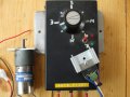
Here is some cheap H drive ICs salvaged from old VCRs Very easy to use & drive. To me these are building blocks if you are using low voltages & small motors. Other salvagable H drives from old VCRs, TA7267. TA7291. TA7288. BA6219. Ive wrecked probably over 60 old VCRS & keep usefull parts. Just a sugestion for younger people pursuing Electronics. Daryl
Thanks, Bill so much for update the circuit. I think you are right, I imight need to break at least 1sec before it revert direction. How to connect 1 sec in between them? I think you know better than me, if you have time, please let me know the break circuit betwen them.
Just theory, but I've made plenty of timers, and I've powered a lot of relays. It would work. The OP has updated the specs for the motor though, so some redesign is required.
OK, this will work, and CR1-4 are optional, but there is still a serious flaw in the concept. I don't think you (the OP) is prepared for the extreme currents you will get when the motor reverses direction. It may be a 1A motor, but it will pull a lot more than 1A doing this trick. Motors are also generators, and there will be considerable back EMF when it is up to speed.
You might think about adding a ½ second delay to allow it to break to a halt. This will involve another timer, but it could prevent problems down the road.
Or you could try it as is and see what happens.
The diodes CR1-4 will probably add life to the relays, but they aren't actually needed. I'm basing this on an earlier discussion I read on an earlier post. CR5 and 6 are not optional, they are required to prevent back EMF from damaging the transistors.
I'm assuming TP5 Input is going to ground or Vcc, don't leave it floating.
As your idea to break the motor of 1 sec before Motor goes revert direction. It mean, the motor goes forward 10 second, stop 1 second and goes revert 10 second.
 Facebook
 Google
 GitHub
 Linkedin