Dual polarity linear power supply, smoothing problem (SPICE model inside)

Thread Starter

FurryLemon

Joined Aug 14, 2016
20
Hello there,

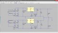
So this is something that I would like to build in a few weeks, It is essentially a variable power supply that will go from +/- 15v to +/- 25v, and one 0v connection, while being capable of supplying up to 1.5A if need be.

So this power supply provides two 30v rectified smoothed inputs into the regulators on the positive and negative sides, I have used a positive voltage regulator on the negative side which regulates the negative voltage. Have a look at the SPICE model included.

Anyway, my problem seems to be when I change the test loads connected across the outputs. If I choose I low resistance then the current being drawn will be large, thats fine, however the ripple increases by quite a bit. For example in the SPICE model, if the regulator supplies +/-25v and there is 1.25A drawn to the 20 ohm load. The ripple is then equal to about 11.5v.

However if I do the calculations using I = (C*dv ) / dt , where dv is the ripple voltage and dt = 1/100Hz, and C = 4700uF.

Then the ripple is 1.25*0.01 / 4700uF = 2.65v , nowhere near as large as 11.5v !

These calculations seem to work when the current being drawn is low. Even If I choose an even larger capacitor and run the simulation for a longer time, the ripple is still large, if not slightly larger.

So how can I reduce this ripple when drawing a larger current ? it also seems to happen when I adjust the output to be 15v and use a small resistance, say 15 ohms, the voltage waveform looks quite odd with quite a bit of ripple.

See my SPICE model, To adjust the regulator output voltage change R-variable for both regulators (1900 for 25v and 1 for 15v, and change the smoothing capacitor to a larger value to see what im talking about.

Any help would be greatly appreciated
thanks.
 

Attachments

SLK001

Joined Nov 29, 2011
1,549
My first guess is that your 4700μF capacitor should be more than a magnitude greater than what it is. And where is your schematic?
 

#12

Joined Nov 30, 2010
18,224
I have used a positive voltage regulator on the negative side which regulates the negative voltage. Have a look at the SPICE model included.
I can't open Spice models, so I can't tell why you used the wrong regulator for the negative supply.
 

Thread Starter

FurryLemon

Joined Aug 14, 2016
20
My first guess is that your 4700μF capacitor should be more than a magnitude greater than what it is. And where is your schematic?
Thanks for replying. The .asc spice file is right at the bottom of my post as an attached file. I use LTSpice. Are you getting an empty schematic when you open it.

The thing is, even with 4700uF i'm not getting the expected ripple I should get. I've even used 10,000uF and twice that.

I can't open Spice models, so I can't tell why you used the wrong regulator for the negative supply.
ahh, sorry, here is an image. It is possible to use this configuration though isn't it ?
I mean this circuit works in Spice, its just the ripple becomes large at larger currents, around 800ma and upwards.
 

Attachments

Last edited:

#12

Joined Nov 30, 2010
18,224
My first guess is that your 4700μF capacitor should be more than a magnitude greater than what it is.
My first run with a calculator shows 2.256 volts p-p ripple...which is good.
The bad part is the 35 V RMS transformer delivering 48 volts to a chip with an absolute maximum input voltage of 30 volts.
Then again, with 2 completely separate transformer windings, you can stack two positive supplies, but it isn't a +/- power supply, it is two positive supplies galvanically isolated.
 

Thread Starter

FurryLemon

Joined Aug 14, 2016
20
My first run with a calculator shows 2.256 volts p-p ripple...which is good.
The bad part is the 35 V RMS transformer delivering 48 volts to a chip with an absolute maximum input voltage of 30 volts.
Then again, with 2 completely separate transformer windings, you can stack two positive supplies, but it isn't a +/- power supply, it is two positive supplies galvanically isolated.
I'll be using the lm317 regulators, LTSpice doesn't have that model. The transformers I'll be using will have two cores supplying 22Vrms which is 31.1V peak.

In LTSpice that 35V is not rms, thats it's peak value, not rms. I made that mistake earlier.

Anyhow, I originally had the two voltages at 31.1v, and the ripple is slightly larger. 13.5v of ripple. At 35v the ripple was 11.5v.
Oh, hang on, the output seems to be clipped slightly when at 35v, because it's over 30v. .Thats why I was reading a slightly less ripple than at 31v. But the ripple is still 13.5v
 
Last edited:

#12

Joined Nov 30, 2010
18,224
I ran the math again. 4700 uf at 100 Hz and 1.5 amps should show a p-p ripple voltage of 2.2567V
Busy right now. Be back in an hour.
 

CEJones

Joined Feb 12, 2016
13
Considering this is a linear supply I think you may need the right part model if you are running this in a simulation. I'm on a phone so didn't look at the simulation but based on properties of linear regulators I have a few suggestions.
1. Make sure you know your regulator's dropout voltage. 11v of ripple tells me the supply is dropping below the output voltage and so the linear passing element is shutting off to prevent reverse current.
2. Check your input voltage waveform across the 4700uF capacitor. Again if this is dropping below the desired output then you're in trouble.
If the input is always above the dropout voltage there will be little to no ripple. The other thing to consider, linear regulators are very lossy and as such some have built in current limits as protection. 35V rms to 25V DC at 1.25A is around 15W dropped in the regulator. If you need to drop such a large voltage at such a heavy current, I highly recommend using a simple buck converter.
Hope this helps.
 

Thread Starter

FurryLemon

Joined Aug 14, 2016
20
1. Make sure you know your regulator's dropout voltage. 11v of ripple tells me the supply is dropping below the output voltage and so the linear passing element is shutting off to prevent reverse current.
2. Check your input voltage waveform across the 4700uF capacitor. Again if this is dropping below the desired output then you're in trouble.
If the input is always above the dropout voltage there will be little to no ripple. The other thing to consider, linear regulators are very lossy and as such some have built in current limits as protection. 35V rms to 25V DC at 1.25A is around 15W dropped in the regulator. If you need to drop such a large voltage at such a heavy current, I highly recommend using a simple buck converter.
Hope this helps.
This does help, thanks. The 35V is not rms it is the peak value of the sine wave. I've changed it to 31v now.

I measured the voltage across the smoothing capacitors and I get pretty much the same large ripple.

Hang on I'll look at to see if the regulator has any form of current limiting.....
Well its rated at 1.5A. So It shouldn't be limited in anyway.
 

#12

Joined Nov 30, 2010
18,224
Right now I am at the opinion that you haven't measured any physical devices. You are simulating and the simulation, "shows". I think this is a simulation problem.
 

Thread Starter

FurryLemon

Joined Aug 14, 2016
20
Right now I am at the opinion that you haven't measured any physical devices. You are simulating and the simulation, "shows". I think this is a simulation problem.
Yeah, that has dawned on me. Its just strange because the simulation does work when there is low current and the maths agrees with it. It's just as soon as the current increases the ripple is a lot larger than it should be. On the output side and across the smoothing capacitor.

Also the same problem occurs still without the negative side of supply connected, as in just the positive side and 0v on it's own.

I'll try a different regulator.
 

crutschow

Joined Mar 14, 2008
34,281
Why did you put 11 ohms of equivalent series resistance in the capacitor model? :confused:
That's much higher than a typical capacitor.
That's your problem.
(Sorry to disappoint you #12 but the simulation is fine. ;))

Select a 4700μF capacitor from the model file and you will see that it's about 0.03Ω.
That gives a ripple of about 1.7Vpp for the load shown.

Attached is an LM317 model you can use.
Put the .sub file in the LTspice sub directory and the .asy file in the sym/powerproducts directory
 

Attachments

Veracohr

Joined Jan 3, 2011
772
Why did you put 11 ohms of equivalent series resistance in the capacitor model? :confused:
That's much higher than a typical capacitor.
That's your problem.
Yes.

Look at this datasheet; you'll see that ESR goes down as capacitance goes up. This isn't even a special low-ESR model, and the ESR for 4700uF is as low as 0.0635 ohms.

http://www.mouser.com/ds/2/88/CKR_CKS series-553026.pdf

Also if you choose a higher current diode like 1N4001, which is much more appropriate for a power supply than 1N4148, you'll get less ripple.
 
Last edited:

crutschow

Joined Mar 14, 2008
34,281
...............
Then again, with 2 completely separate transformer windings, you can stack two positive supplies, but it isn't a +/- power supply, it is two positive supplies galvanically isolated.
But you certainly can connect the negative of one to the positive of the other to create a +/- supply.
 

Thread Starter

FurryLemon

Joined Aug 14, 2016
20
Why did you put 11 ohms of equivalent series resistance in the capacitor model? :confused:
That's much higher than a typical capacitor.
That's your problem.
(Sorry to disappoint you #12 but the simulation is fine. ;))

Select a 4700μF capacitor from the model file and you will see that it's about 0.03Ω.
That gives a ripple of about 1.7Vpp for the load shown.
oh no!, The thing is, I actually didn't change the resistance, I selected the capacitor symbol then I changed it to the first polarized cap model there is, and that model shows that it has an 11 ohms resistance. So I didn't change it, but I'll admit, I should of checked that. Thank you.

Yes.

Look at this datasheet; you'll see that ESR goes down as capacitance goes up. This isn't even a special low-ESR model, and the ESR for 4700uF is as low as 0.0635 ohms.

http://www.mouser.com/ds/2/88/CKR_CKS series-553026.pdf

Also if you choose a higher current diode like 1N4001, which is much more appropriate for a power supply than 1N4148, you'll get less ripple.
Right, ok, thanks.

Hello,

@Veracohr
Even the 1N400X will be to small.
Better look for the 1N540X series.

Bertus
Ok will do.

That doesn't show in the .JPG of post #5 so I was without awareness of the resistance.

Yeah, I know. That's what galvanically isolating them accomplishes.
Thanks for helping me. Sorry It was a stupid problem !

Thank you for the help guys.


But you certainly can connect the negative of one to the positive of the other to create a +/- supply.
Great, so It can work without the need of a negative regulator and instead using two positive regulators.
It's just that as I was searching through this forum I noticed someone had a similar circuit to me, two positive regulators instead of one +ve and one -ve regulator, and a few people insisted that it would not work. That you would definitely need a negative regulator. I think they mentioned something about the current not having a return path. But in my case there is a return path, it can go from the -ve or +ve output back to the 0v connection, right?
 

crutschow

Joined Mar 14, 2008
34,281
...................
Great, so It can work without the need of a negative regulator and instead using two positive regulators.
It's just that as I was searching through this forum I noticed someone had a similar circuit to me, two positive regulators instead of one +ve and one -ve regulator, and a few people insisted that it would not work. That you would definitely need a negative regulator. I think they mentioned something about the current not having a return path. But in my case there is a return path, it can go from the -ve or +ve output back to the 0v connection, right?
When they say you cannot use two positive regulators, they are usually referring to a supply with a single, center-tapped transformer winding to get the two voltages.
For that situation, where the two voltages have a common ground, you would need a negative regulator for the negative voltage.

With isolated supplies, as you have, you can connect the supplies any way you like, so you can have a plus and minus supply, or two supplies of the same polarity but different voltages.
 
Top