Dual polarity to two switches

Thread Starter

Mikhail2023

Joined Nov 26, 2024
8
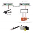
Hi…I’m new and very green when it comes to circuits…but I was wondering if someone here might help…I have a solar tracker controller that operates a linear actuator by reversing it’s polarity. It simply switches the neg and pos in order to rotate the 12 volt motor either way…causing the linear actuator to either retract or protrude, get shorter or longer. I would like to change the 12 volt linear actuator for a 12 volt two way hydraulic pump that will operate a two way hydraulic ram. But the ram has two solenoids to operate the ram, either out or in. It has two switches, close one contact and it opens, closed the other contact and it closes. Is there any way I can get the polarity switch to operate two separate switches. So when the polarity is neg it either opens or closes the ram and visa versa. Sorry for the long winded question, also, I’m posting here because I’ve no idea if there is a more appropriate forum…sorry….hope someone can throw some light on this…many thanks..Mike
 

ronsimpson

Joined Oct 7, 2019
4,647
I don't have enough information yet. Here are some options you might have now.
1) You might have a single switch where NC1 and NC2 are one switch that has two positions, Up or Down. Forward or Reverse.
2) You might have a single switch where NC1 and NC2 are one switch that has three positions, Up/stop/Down.
3) You might have two switches where NC1 & NC2 are different switches, having two positions. Up&Up=forward, Down&Down=Reverse, Opposite (1&0 or 0&1)=stop.
Do you have or want one of these options or yet something different. I think your controller is wired like (3).
1738848840186.png
 

Tonyr1084

Joined Sep 24, 2015
9,744
I believe the question is about controlling solenoids that operate a hydraulic ram, not reversing a DC motor. To answer this, I’d need a hydraulic schematic to better understand and possibly find a solution.
 

crutschow

Joined Mar 14, 2008
38,321
Need to know if one side of the motor voltage goes to zero, when the other is positive for both states of the motor activation.
 

Thread Starter

Mikhail2023

Joined Nov 26, 2024
8
Wow! Thanks Ron….much of that went over my head but i can just about work out the diagram…you say you don’t have enough info right now so I’m gonna try and make things clearer with a diagram…but it sounds like it’s possible…just knowing how…I’ll get back later…Mike
 

BobTPH

Joined Jun 5, 2013
11,463
1738854700231.png

This works if the reversible voltage and current capacity on In1 and In2 is what is needed to operate the two solenoids. If the solenoids have a common connection already, just use that as the bottom one. If the voltage is different, same wiring, but L1 and L2 are relays that operate the solenoids.
 
Last edited:

Thread Starter

Mikhail2023

Joined Nov 26, 2024
8
I’ve made a diagram but not an electrical schematic…apologies….my current set up on the left has two wires from the controller to the linear actuator motor. The controller reverses the polarity to enable the motor to turn both ways, in this case, it’s north and south. The planned set up on the right has the same two wires that change polarity but connected by magic to a hydraulic controller with two contact switches. Can it be done? Mike
 

Attachments

ronsimpson

Joined Oct 7, 2019
4,647
Thanks now we know how the controller works inside. It is like the picture in post #2.
Can you open up the orange switch box and take a picture of the insides? We might be lucky and do post #7. or We might have to add some parts like a relay or two.
 

sparky 1

Joined Nov 3, 2018
1,218
A lift gate for a box truck has an electric motor and hydraulic pump unit. The solar panel assembly having unspecified weight.
The power cables are like a starter motor possibly 4 gauge while others are 18 gauge.
The lift seems to have most of the essentials to construct a manual override.
Link below includes a schematic p.17 it shows 3 contactors having sufficient rating. The general pump control wiring might be similar.
Possibly like the picture posted, that is the orange control box and cable harness, identifying those terminals would be helpful.
Advise needed close-up photo inside the orange switch box that depicts wire color and their relative switch terminal configuration.

It should be noted that the lift gate specifies recommended parts be used, the hydraulic version could be faster using more power over shorter time.
Many DIY lift gates have design flaws and end up scrap and later replaced with a quality tested and proven lift. Might expect some reinforcement.

Model
 
Last edited:

Tonyr1084

Joined Sep 24, 2015
9,744
Is the hydraulic pump reversible?

Just like the sun roof on my old Hyundai Sonata (2007), push one button and a relay activated to drive the motor (for example) open. Press the other button and the other relay activated and drove the motor to close.

If the motor is not reversible then in order to achieve slewing of the antenna you're going to need hydraulic valves that can be actuated electrically.
I would like to change the 12 volt linear actuator for a 12 volt two way hydraulic pump that will operate a two way hydraulic ram.
If this IS a reversible motor then it must be a closes system, no way to check fluid levels or fill it without opening a fill port.
 

MisterBill2

Joined Jan 23, 2018
27,181
Hydraulic servos are often controlled by a single hydraulic servo valve that gets a bipolar drive, depending on which way to drive and how fast. THAT could be an alternative. The question now becomes one of voltage and current capability. But certainly a hydraulic servo valve can control the cylinder with just one device and possibly no circuits changed.
 

Thread Starter

Mikhail2023

Joined Nov 26, 2024
8
Thank you for the very knowledgeable feedback…I’ve saved the schematics and will explore their possibilities… I guess I was just asking if a single dual polarity feed could basically turn two switches on or make just a simple contact like a light bulb…once I’d sorted that, I’d explore how it could be applied to the hydraulic switches….thank you again..Mike
 

MisterBill2

Joined Jan 23, 2018
27,181
Hydraulic valves with a single coil but switching both ways are also available and they cost quite a bit less than servo valves. The big benefit would be NO CIRCUIT CHANGE AT ALL. Just connect in place of the DC motor. So about as simple a change-over as you can get.
 

AngelaD

Joined Oct 8, 2024
2
Okay, so you're wiring up two switches with a dual polarity setup. Think of it like this: you've got two switches, and each one needs to be able to control the same light (or whatever it is you're wiring). Dual polarity, sometimes called three-way switching, is how you make that happen.
Basically, you'll have a "common" wire that goes to the light, and then two "traveler" wires that run between the two switches. Each switch then connects to the common wire in one position, and to one of the traveler wires in the other position. When both switches are in the same position (both up or both down), the circuit is complete, and the light is on. Flip either switch, and you break the circuit, turning the light off.
It sounds a bit complicated, but it's actually pretty straightforward once you get the hang of it. There are tons of diagrams and videos online if you search for "three-way switch wiring diagram" or "dual polarity switch wiring". Visuals are super helpful for this kind of thing.
Just remember to always turn off the power at the breaker box before you start messing with any wiring! Safety first! And if you're not totally comfortable with electrical work, it's always best to call a qualified electrician. They can get it done quickly and safely.
 

MisterBill2

Joined Jan 23, 2018
27,181
FIRST, this IS NOT a "three-way switch" question, based on post #1! It IS an "off or either direction" control discussion and so there are two different "ON" conditions.
NEXT, discussing the desired hydraulic control scheme that includes a "cylinder stopped in a partial stroked" position, there are not two isolated hydraulic valves. There would be a single THREE POSITION, FOUR PORT hydraulic valve with two separate coils, usually. BUT there might also be a single DC coil reversing valve with a maintained center-off position, driven by a reversable polarity voltage. My original suggestion was a FOUR PORT servo valve, and then a FOUR PORT Proportional hydraulic valve. Either of those will provide the required control with no circuit change, although the voltages may need to be changed.
 
Top