Facebook
 Google
 GitHub
 Linkedin
HI EVERONE
could you help me?
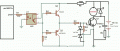
I want to design circuit FOR driving Gate_IGBT (GT60N321)
to control the speed of dc motor (180 volt _ 2 HP)
I want to control the Igbt-Gate by pic microcontroller (pwm_pin)
and this is the circuit but it isnot work

could you help me?
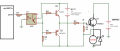
I want to design circuit FOR driving Gate_IGBT (GT60N321)
to control the speed of dc motor (180 volt _ 2 HP)
I want to control the Igbt-Gate by pic microcontroller (pwm_pin)
and this is the circuit but it isnot work