Hello @du00000001
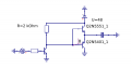
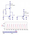
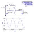
with the simulation software I didn't get any improvements with the push-pull/Totem_Pole circuit. There, too, the problem is with the large capacity of the atomizer disc, as you can see in the picture
I have rebuilt this circuit, but Vpp probably only comes to 10V in the real circuit because of the damping. Also, the capacitance of the atomizer is very dependent on mechanical stress, so that an oscillating circuit seems impractical.
Re #21
Remove the resistor - it's not necessary for a totem-pole driver stage!
In addition you will need a P-channel MOSFET for T2 and have to adapt the gate driving circuit for T2. But basically the totem-pole circuit would be more complex to prevent shoot-through when switching.
Re #22
Remove this fancy capacitor and the 100R - it doesn't do much good at this point!
Then add an inverting transistor stage (NPN transistor, 2 or 3 resistors, supplied from the higher voltage) between your square signal source and the emitter follower's base connection (for level shifting purposes) and increase the voltage for the piezo according to your needs (48 V).
Remove the inductor too, or adjust it according to the needs. (With the inductor you'd better check the voltage at the connected emitters to make sure you don't exceed the transistors' ratings - especially reverse voltages. Simulations do not care about the components' ratings! ) Or remove the inductor and replace it with an appropriate resistor.
In the end you will drive the piezo with a square or triangle wave, not with a sine. But I don't think this will hurt much.
Re #21
Remove the resistor - it's not necessary for a totem-pole driver stage!
In addition you will need a P-channel MOSFET for T2 and have to adapt the gate driving circuit for T2. But basically the totem-pole circuit would be more complex to prevent shoot-through when switching.
Re #22
Remove this fancy capacitor and the 100R - it doesn't do much good at this point!
Then add an inverting transistor stage (NPN transistor, 2 or 3 resistors, supplied from the higher voltage) between your square signal source and the emitter follower's base connection (for level shifting purposes) and increase the voltage for the piezo according to your needs (48 V).
Remove the inductor too, or adjust it according to the needs. (With the inductor you'd better check the voltage at the connected emitters to make sure you don't exceed the transistors' ratings - especially reverse voltages. Simulations do not care about the components' ratings! ) Or remove the inductor and replace it with an appropriate resistor.
In the end you will drive the piezo with a square or triangle wave, not with a sine. But I don't think this will hurt much.
Hallo @du00000001
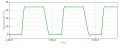
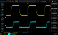
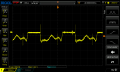
Thanks for your hints with the upper transistor. I have found two transistors here with which I can switch as a "totem pole" according to the simulation. But it doesn't work in the real bread-board circuit, as you can see from the diagrams. And i dont now why
This are the digramms from rhe software:
and here the Oszi-graphs from the basis of real circuit:
and this is the real output:
I think the Voltage on the Basis of the Transistors is high enough to switch then fast?
It doesn't even work in the simulation (if you know what to probe). Check how many diodes and resistors are used in the totem-pole example link I provided! (Hint: they are really required.)
But you've got the components for a complementary emitter-follower now:
Swap the 2N5*. Tie the emitters to the middle (point A) and their bases together.
Remove 2N222A1, RL2, RL3 and the 1k resistor to its base.
Remove the fancy diode currently residing between the base of the lower 2N5* and GND.
If your want to protect something with diodes: connect 2 diodes to C and E of each 2N5* - cathodes up.
Connect the collector of the remaining 2N2222 to the connected bases of the 2N5*
Could be RL = 10 k is a bit high impedance. 1 k is expected to perform better but would burn more than 0.5 W on average. Use a resistor rated for that, or multiple individual resistors in series or parallel to achieve 1 k total resistance.
thanks @du00000001
Your hints have let me find a circuit with only five components that works
But the manufacturer's boards actually bring 100V VPP instead of the 44V I wrongly assumed. With this high value, it is probably easier to use coils than to follow the safety regulations for high voltage?
OK, the arrangement with two coils is commonly called a TRANSFORMER, which is the common term for many of us. A transformer would certainly provide the isolation to separate the 100 volts supply and reduce the potential shock hazard. It could also improve the efficiency of power coupling to the PIEZO elements. It may even help to cure some of the strange waveforms provided by the simulator.
The creation of a transformer for this application will require knowing the voltages that are intended for both sides, and the frequency, as well.
thanks @du00000001
Your hints have let me find a circuit with only five components that works View attachment 363048
But the manufacturer's boards actually bring 100V VPP instead of the 44V I wrongly assumed. With this high value, it is probably easier to use coils than to follow the safety regulations for high voltage?
When considering the use of an inductor or a high-frequency transformer you'd better add the 2 free-wheeling diodes to protect the transistors from getting fried due to "backlash" from the inductance. Just in case . . .
Whether you try something resonant (inductor in series with the piezo) or a transformer (like in the original circuit) doesn't matter much, although I think the transformer circuit is easier to dimension. ("gate drive transformers", "pulse transformers" or whatever they are called are available with turns ratios at least in the 1:1 .. 1:3 range).
Re "100 V": 100 V are 100 V - it doesn't matter that much whether they come from a power supply or from some inductance. (OK - the power supply might be able to deliver more power than this circuit. But there will be not much difference in how it hurts if you touch the wrong leads.)
I will try to get from 220V to 12V Transformer backwards from 5V to 100V with 108kHz. (But they are built for 50Hz). And to switch these 100V/108kHz to eight channels with transistors. Or have anybody a Link to a usable Transformer to buy?
I will try to get from 220V to 12V Transformer backwards from 5V to 100V with 108kHz. (But they are built for 50Hz). And to switch these 100V/108kHz to eight channels with transistors. Or have anybody a Link to a usable Transformer to buy?
IT will not work to use a 50 Hz iron core power transformer at 108 KHz, I suggest copying the kind of transformer used in the original, but with the required turns ratio and a suitable wire size.
I will try to get from 220V to 12V Transformer backwards from 5V to 100V with 108kHz. (But they are built for 50Hz). And to switch these 100V/108kHz to eight channels with transistors. Or have anybody a Link to a usable Transformer to buy?
I gave you keywords for transformers that might fit. At Mouser they are to be found here: https://www.mouser.de/c/power/transformers/pulse-transformers/
When powered from an adjustable power of 48 V max., a 1:2 or 1:3 transformer should do. Maybe select one, model IT in the simulation, evaluate and buy then. (They are quite cheap - p&p might exceed the components' costs )
@MisterBill2 @du00000001
Thank you for your support
I have read that with higher frequency the transmission ratio of a transformer increases and also the eddy currents. I can't open the link to mouser, every link to mouser opens a blank page for me. If I wanted to wind a transformer myself and switch it with transistors and freewheeling diodes, would I have to pay attention to a minimum resistance of the primary winding? Or can I simply wrap five windings with 0.5mm enameled copper wire around plastic and the secondary winding on top?
Eddy currents only flow in conductive materials. At 100 kilohertz you would not be using an iron core, possibly ferrite, but it could easily be done with an AIR CORE! No eddy current losses and no hysteresis losses. So those losses will simply not be any problem.
If you really reside at Rheinland-Pfalz, it shouldn't be a problem to go to mouser.
Maybe start with "manually" going to www.mouser.de, answering their "I'm no robot" captcha, clicking the link afterwards...
The transformers offered are most likely ferrite core ones (or iron powder cores - certainly not "iron core"). And no - the transfer ratio only depends on the ratio of the number of windíngs - not on the frequency.
When considering winding yourself, I'd use a ring core and wind on opposite sides of the core. Air cores are not that great - you want to transfer some energy and neither the coupling between the windings nor the inductance achieved is great, so the primary current will skyrocket.
Just because a transformer is "air core" does not mean heavy wire and wide spacing! As long as the insulation is adequate for the voltage used the turns can be touching. The science of transformers is very mature so there is a whole lot of information available.

 Facebook
 Google
 GitHub
 Linkedin


 ) Or remove the inductor and replace it with an appropriate resistor.