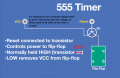
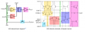
Is this wrong info about PNP transistor? This transistor turns on when Vb<Ve. So when Reset voltage is 0,7 volts lower than VCC voltage this transistor turns on. In this case Reset needs to be held LOW not HIGH. Is this video incorrect?
Even worse than that, the notion of resetting a flip-flop by cycling power to it is a disaster in waiting. For the vast majority of flip flops, there is no guarantee what state the flip flop will power up in or that it will be the same from one power cycling to the next (though they often will).
It appears that this slide is attempting to describe the internal working of a 555 timer and butchering it badly. Ignore that site.
That's not too surprising -- a lot of websites blatantly steal content from other websites without even attempting to evaluate whether it is accurate or not.
Even worse than that, the notion of resetting a flip-flop by cycling power to it is a disaster in waiting. For the vast majority of flip flops, there is no guarantee what state the flip flop will power up in or that it will be the same from one power cycling to the next (though they often will).
It appears that this slide is attempting to describe the internal working of a 555 timer and butchering it badly. Ignore that site.
Good point. It sucks when you are trying to learn electronics from youtube but you can't know which video has correct info. This video has almost million views.
When you consider that content on YouTube isn't peer reviewed, you're rolling the dice when you don't know enough to determine whether what you're being told is correct.
In your case, when you see a "schematic" drawn in an unconventional way, move on.
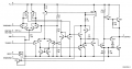
This 555 schematic from National Semiconductor is drawn more conventionally. Note how Q25 is drawn with the emitter on top. This is the preferred orientation in most cases.
The timer reset function doesn't apply power to the flip flop or the timer. It discharges the timing capacitor and resets the flip flop which forces the timer output LOW.
As shown in the internal schematic, Q25 (the Reset transistor) does not control the power to the latch circuit. And, its emitter is not tied to Vcc. And, its collector is clamped to one Vbe drop above GND by Q14.
Yes, the Reset input affects the latch operation, but not in the way shown in the graphic.
Fun Fact: Not all 555's operate the same way. The original circuit never was patented by Signetics, and some of the clone parts have slightly different operation. There is thread about this on this site, but I suck at finding old threads.

 Facebook
 Google
 GitHub
 Linkedin