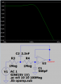
If you take U4b and turn it through 180° along with the wire on its output, it will drop in place and make an amplifier with a gain of 11. A rather pointless amplifier as it is followed by an attenuator which reduces the gain by a factor of 55.
That leaves us with a low pass filter with a cutoff frequency of 143Hz.
You don’t say the frequency of the squarewave, but the output won’t be a sine wave, it will be a squarewave with the edges rounded a bit.
If your client thinks it will make a sine wave, then he’s the sort of client to avoid.
Certainly there are drafting errors here. U4b has been "flipped" about the wrong axis at least twice. So the CAD drafter has no electronic understanding, it seems. It seems like the intent was to stabilize an oscillator with a square wave, which is valid, but not achieved in the circuits shown.
With positive feedback as shown in that attachment shown in post #7, U4b will provide a fair squared wave, as it goes from one saturated state to the other.
To produce a sine wave from a square wave it needs to pass through a very high "Q" filter, which doe not follow U4b. Another filter section similar to U4a could come ort of close to a sine wave at the pass frequency.
There’s more problems. The filter has a Q of 1, so a gain of 1.2
I’m guessing that the opamp is powered off the same rails as the logic, so the squarewave is the full voltage of the power supply, but a TL072 is neither rail to rail input nor output.
And where does the mysterious 0V connection (which looks as though it ought to be half supply) come from?
It certainly looks like a number of goofs by the CAD operator, who iis not the designer. It may be that the drawing program is new to either or both.
Generating a sine wave from a pulse from a decade counter will be a challenge, and while it may be possible with the components shown, the circuits shown will not do it.
To provide useful advice we need to know the frequency of the desired sine wave, and knowing the voltages both supply and the output, peak to peak. at that point the circuit can be created. Then we can check the drafter's work.
Yes, the 4018 will work rather well, BUT it is not a binary counter and so the resistors must all be the same value. That makes it easier to set up and also educes the glitches that would be created by a binary ripple counter, such as the 4020, 4024, or 4040. So really the 4018 is the better choice. What will be important is to properly terminate all of the unused inputs.
Also, it looks like there can be 5 bit resolution with the steps, and so the input frequency will need to be higher. I guess.
The antique TDA2003 output amplifier has been obsolete and not available for a number of years
The Q of the lowpass filter is too high. When the opamp has a gain of 1 then the feedback capacitor value should be double the capacitor to ground capacitor value.
The antique TDA2003 output amplifier has been obsolete and not available for a number of years
The Q of the lowpass filter is too high. When the opamp has a gain of 1 then the feedback capacitor value should be double the capacitor to ground capacitor value.
2:1 gives Butterworth, equal values give critically damped.
I wonder if the idea was to put the fundamental frequency at the peak of the filter. Even so, it doesn't give a good sinewave. An elliptic filter with notch at the third harmonic works better but is difficult to align.
As the input signal is already too large for the amplifier, a gain of >1 only makes things worse.
This circuit, given o the TS by a client, reminds me of long ago a client of my employer asked us to do a "build to print" of a circuit that they had been given. I told them that we could do that, but that it would not work. I provided an explanation of why it would not work. Two days later we got a request to quote building a circuit that would do what they required it to do. We built it and it worked and they were happy.
What we are seeing in this instance is similar. To produce a single sine wave frequency I like an LC tuned circuit that can be set to ringing by the input pulses. Fairly stable and not so complex to design. Definitely "old school" technology, though.
My very low distortion sinewave oscillator uses a CD4018 making 10 steps then it is filtered with an adjustable frequency switched-capacitor Butterworth lowpass filter IC that uses the same clock as the CD4018.
My distortion analyzer also uses the same clock and a similar switched-capacitor notch IC.
 Facebook
 Google
 GitHub
 Linkedin