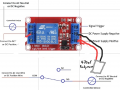
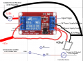
Does this look correct

Thread Starter

Ynkeeeboy12

Joined Aug 2, 2026
1
I'm wanting to smooth a PWM LED signal being used as a trigger for additional lighting. Right now it has some relay chatter at fade on and fade off. Everything is 12v and the trigger is the negative line of the LED being tapped (Toyota). What I've researched says to use a 470ųF rubycon capacitor across the pos and neg inputs. Also wanting to double check check the orientation is correct. I've seen one of these firecracker with someone else.
 

Attachments

WBahn

Joined Mar 31, 2012
33,072
Please do not connect the DC power supply to the power line.
You need a power supply.
View attachment 370483
Why not?

What power supply is he going to use, if he can't use the 12 V power from his Toyota's battery?

The capacitor across the DC power inputs for the control side is unlikely to do what he wants (though there's no harm and some benefit, especially since it doesn't look like there's any decoupling capacitor on board (but maybe I'm just not spotting it).

He says that it is chattering at fade in and face out, which argues that the problem is a lack of hysteresis, which would be a problem with or without the use of PWM, but the PWM probably aggravates it.
 

ronsimpson

Joined Oct 7, 2019
4,774
I see now. I looked at the picture, and it showed the relay connecting to the power line. If everything is 12V then connect it up.

I assume the Negative side of the LEDs is connected to ground.
Car voltage is 12V when the car is not running and close to 14.5V when the engine is on. The relay has a maximum voltage rating (on the coil) of 15.6V. That is close to the 14.5V of most cars. The relay should operate down to 9V. So, the relay will work well with the engine off and it will run good and worm while running.
The capacitor can be almost any type of Electrolytic. Watch the polarity (+ or -) I would not use the 16V type but go for 25V or more. I don't see the need for a large 470uF. 100uF or 47uF or whatever you can find.
1786885605146.png
 
electromechanical relay are way too slow for PWM. they need 10-30ms to change state.
they are meant to turn something ON or OFF... but only from time to time.

PWM is fast changing signal that turns on/off anywhere from few hundred to tens of thousands of times - every second. and for that for PWM you NEED solid state device such as MOSFET.

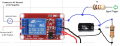
to make relay turn on/off cleanly without chatter, you need to add capacitor across trigger input. probably also need to buffer it (at least a diode or resistor before capacitor).
by using correct values it should be possible to make the relay not chatter. but... the load (lights) that relay is powering will be either ON or OFF... if you are expecting to see the fade in/fade out that PWM is known for, you must use solid state device.


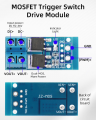
This is an example of MOSFET module but... things like this are low side switch. pretty sure you would want high side switch (unless you want to run extra wire).

and... if the PWM frequency is low, you can also use solid state relay.

1786976383421.png


if you are ok with circuit as is, but just want to remove chatter, something like this should work (values are just for orientation):
1786977486515.png
 
Last edited:

WBahn

Joined Mar 31, 2012
33,072
I think he is making the chatter with a PWM signal. Could be wrong it happens.
While I think the chatter is probably being aggravated by the use of PWM, notice that he talks about it being an issue when the signal is fading in or out -- i.e., changing slowly. That argues pretty strongly for it being du to the lack of hysteresis on the comparator's threshold.
 
Top