Does anyone know how a linear expansion valve works electrically?

Thread Starter

lsheaf

Joined Jan 22, 2024
19
I own a small handheld manual tool that can open and close the mechanical part of a linear expansion valve but how is this done electrically with a coil?
For reference, this is for an air conditioning system.
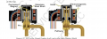
This is what the service manual gives me for troubleshooting one the coil.
Screenshot 2024-07-28 at 6.25.48 PM.png
 

LowQCab

Joined Nov 6, 2012
5,101
This is a simple "Stepper-Motor",
it's the same type of Motor that controls the Idle-Speed of the Engine in your Car.

They are not necessarily designed for Speed, or Brute-Power,
but more for precise-positioning, usually via a Threaded-Rod, one step at a time.

There are plenty of specialized-Chips designed to control this type of Motor.

Note: The fact that the 2-Coils are "Center-Tapped" indicates a specific-type of Stepper-Motor,
requiring a Driver-Chip that is compatible with this particular Winding-Configuration.
.
.
.
 
Last edited:

MisterBill2

Joined Jan 23, 2018
27,164
That is indeed the circuit of a "Unipolar" type stepper motor, that applies a (usually positive) voltage to the center connection of both windings and then controls which of the four are energized by four (open collector) NPN transistors.
 

Thread Starter

lsheaf

Joined Jan 22, 2024
19
This is a simple "Stepper-Motor",
it's the same type of Motor that controls the Idle-Speed of the Engine in your Car.

They are not necessarily designed for Speed, or Brute-Power,
but more for precise-positioning, usually via a Threaded-Rod, one step at a time.

There are plenty of specialized-Chips designed to control this type of Motor.

Note: The fact that the 2-Coils are "Center-Tapped" indicates a specific-type of Stepper-Motor,
requiring a Driver-Chip that is compatible with this particular Winding-Configuration.
I would like to use something that I could interface with an Arduino board.
.
.
.
Thank you for the reply.
Can you elaborate on what kind of driver-chip I would need to control this mechanism?
 

Thread Starter

lsheaf

Joined Jan 22, 2024
19
That is indeed the circuit of a "Unipolar" type stepper motor, that applies a (usually positive) voltage to the center connection of both windings and then controls which of the four are energized by four (open collector) NPN transistors.
Thank you for the reply,
Can you elaborate more on exactly how this works? and what is needed to control this mechanism?
How is the direction controlled by energizing the transistors?
 

LowQCab

Joined Nov 6, 2012
5,101
Not "just any Controller" will work.
The Motor is designed to operate with a Controller that supplies a specific, and limited, amount of Current.
The Controller is not only a "Polarity-Switcher", but also a "Current-Regulator".

Unless the specifications of the original Stepper-Motor-Controller can be obtained,
this Motor, or Valve, can not be used without the possibility of accidentally burning-up the Motor-Windings.
.
.
.
 

MisterBill2

Joined Jan 23, 2018
27,164
Thank you for the reply,
Can you elaborate more on exactly how this works? and what is needed to control this mechanism?
How is the direction controlled by energizing the transistors?
Yes, I could go on in a lot more detail, but NO, I will not. Stepper motors are a fully mature technology and not only the basics but most of the insights are published and presented very clearly.
 

MisterBill2

Joined Jan 23, 2018
27,164
If the need is for stepper control for any commercial project I seriously suggest using a driver made by the stepper manufacturer that is optimally matched to the motor. My reasoning is that if ever pieces need to be replaced, the client will be able to quickly know just what, and from where.

Of course, the only stepper motor in a machine that failed was one that the mechanical team mounted where it was under water during every machine cycle. It was not even a water resistant motor.
 
Last edited:

MaxHeadRoom

Joined Jul 18, 2013
30,557
If the need is for stepper control for any commercial project I seriously suggest using a driver made by the stepper manufacturer that is optimally matched to the motor.
Personally I don't favor applying restrictions on my sphere of work, I would much rather have options.
When I would retro-fit a machine for CNC, I would mix and match makes of drives and servo motors at will. ! :cool:
 

MisterBill2

Joined Jan 23, 2018
27,164
Back to the original question from post #1. The motor rotates in small steps as the drive power is switched in a repeating pattern among the four halves of those winding connections. The benefit of this scheme is that the motor can be driven any small distance quite accurately and as slow as is required for the adjustment.
 

MisterBill2

Joined Jan 23, 2018
27,164
I suggested matching the driver to the motor because it will then not take as much effort to produce a good match. NO OTHER REASON. Perhaps the TS is not a master servo tech? Not everybody has 30 years of stepper motor experience.
 
Top