 Facebook
 Google
 GitHub
 Linkedin
Gear used:
3 MIDI sources: 486 DX2/66 PC, vintage Macintosh through a midi interface box, regular synth midi controller
3 MIDI destinations: Roland MT-33, Roland Sound Canvas 88ST, Kawai LG-Mega
All of these are known to work, I have used them extensively under every combination.
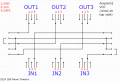
Goal: to make a functional 3 in, 3 out switch that selects one in and one out at any given time.
Gotcha: I can't use the regular IN->THRU method of chaining the destination devices together because only my Roland MT-32 has that port and none of my other devices have it.
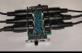
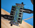
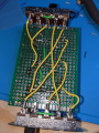
I made a perfboard that connects pins 4 and 5 of the midi sockets together. I use two double pole, quadruple throw (one throw is redundant under this solution) switches. As for the central GND pin, I simply soldered a path and some wires to connect all 6 devices together, which is where the potential problem might arise from.
i have tested every single one of the 9 possibilities with most of my devices and the wiring is sound, so the perf board is properly verified to work one path at a time.
Now, onto the problem. If I leave all the devices connected, and just the one source powered and the one destination powered, the signal doesn't go through. The scenario I'm most interested in is to have my Mac SE/30 running Cubase and sending midi signals through its modem serial port, through a midi interface box, from which comes an OUT midi cable, into my 3x3 switch, followed up with the cable that goes to my Roland SC88ST.
If the cable that goes from my interface to my switch is disconnected, I see my midi interface light up with activity consistent with the music. If I reconnect that cable to re-establish the midi path, the activity LED dims a little and stays static (no signal gets through).
If I then disconnect every unseeded devices from my 3x3 switch but only keep the 2 strictly necessary ones, it works again.
Possible explanations: 1) the various GNDs interfere together and "drown" the signal strength somehow 2) the aging power supply of my Mac SE/30 is marginally not powerful enough to push through the totally wired up switchbox 3) these 6 gnds shouldnt be wired together?
I have a scope to diagnose the difference between different connection scenarios and could post pics in followups but I would greatly appreciate some guidance to zero in on the wrong assumptions I might have about this project.
3 MIDI sources: 486 DX2/66 PC, vintage Macintosh through a midi interface box, regular synth midi controller
3 MIDI destinations: Roland MT-33, Roland Sound Canvas 88ST, Kawai LG-Mega
All of these are known to work, I have used them extensively under every combination.
Goal: to make a functional 3 in, 3 out switch that selects one in and one out at any given time.
Gotcha: I can't use the regular IN->THRU method of chaining the destination devices together because only my Roland MT-32 has that port and none of my other devices have it.
I made a perfboard that connects pins 4 and 5 of the midi sockets together. I use two double pole, quadruple throw (one throw is redundant under this solution) switches. As for the central GND pin, I simply soldered a path and some wires to connect all 6 devices together, which is where the potential problem might arise from.
i have tested every single one of the 9 possibilities with most of my devices and the wiring is sound, so the perf board is properly verified to work one path at a time.
Now, onto the problem. If I leave all the devices connected, and just the one source powered and the one destination powered, the signal doesn't go through. The scenario I'm most interested in is to have my Mac SE/30 running Cubase and sending midi signals through its modem serial port, through a midi interface box, from which comes an OUT midi cable, into my 3x3 switch, followed up with the cable that goes to my Roland SC88ST.
If the cable that goes from my interface to my switch is disconnected, I see my midi interface light up with activity consistent with the music. If I reconnect that cable to re-establish the midi path, the activity LED dims a little and stays static (no signal gets through).
If I then disconnect every unseeded devices from my 3x3 switch but only keep the 2 strictly necessary ones, it works again.
Possible explanations: 1) the various GNDs interfere together and "drown" the signal strength somehow 2) the aging power supply of my Mac SE/30 is marginally not powerful enough to push through the totally wired up switchbox 3) these 6 gnds shouldnt be wired together?
I have a scope to diagnose the difference between different connection scenarios and could post pics in followups but I would greatly appreciate some guidance to zero in on the wrong assumptions I might have about this project.
Attachments
-
 872.3 KB Views: 16
 -
 35.5 KB Views: 18
 -
 1.1 MB Views: 18
 -
 1.7 MB Views: 12

")


