 Facebook
 Google
 GitHub
 Linkedin
Hi everyone,
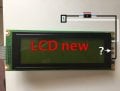
I need to replace a display of my Korg T3 synthesizer to one with backlight.
I took a new LCD from a old mixer KORG D12, (both are a 240x64 dots and they have the same number of pins 22 )
The question is:
The new lcd from the mixer not use a small cable (grey, with 2 thinners black and white), but the original yes.
Onething I noticed is the last pins 21,22 in the new display are not connected because the ribbon has 20 pins.
How can I connect it to make it work the backlight?
I pluged to my synth and seems to work, but not backlight.
I attach some photos.
Thank you very much.
Attachments
-
 430.3 KB Views: 12
 -
 343.9 KB Views: 12
 -
 281 KB Views: 11
Last edited:

")


