Discrepancy between CE Transistor circuit - calculated, modelled, and physical Vc measurements.

Thread Starter

bagorats

Joined Jan 26, 2025
6
G'day Everyone,

I'm re-commencing my electronics journey that started in the early 80s when I interfaced my Tandy Armatron to my Apple ][ (which I still have). As you can imagine things got crazy from there.

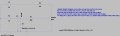
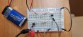
I've calculated resistors sizes for a 2N25551 common emitter - using it as a basic switch to work my way back through the basics. I prefer to use a pencil, calculator and a ruler (I'm a 'the map is not the territory' kind of person) but also put together the simple circuit in LTSpice (image attached). Physical model attached.

So I compare the calculated, modeled and actual measured VB & VC . Paper calculations match the model, transistor is Saturated if I'm reading everything right. Measured VB also matches the (calcs, digital model, physical model), but measured VC is 1.43V which suggests the transistor is Active.

All measurements were taken to Common from Base & Emitter.

I didn't blow up the Apple ][ but I'm missing something fundamental here and all my forum lurking and reading hasn't yielded much.

Appreciate any guidance you could provide.

Regards,

Geordie.
 

Attachments

Thread Starter

bagorats

Joined Jan 26, 2025
6
The 2n5551 has very low Hfe at 100mA Ic. Roughly about 20 only.
Use 2n2222 rather.

in
View attachment 341616
So - steep gradient Ic vs. Hfe probably means small changes in the real circuit (resistor tolerances etc..) means hfe can climb/fall steeply with any variation? That would make sense. I'll see about reducing Ic in the real circuit and see where that takes me - Jaycar should be open in a few hours if I don't have a 2222. Thank you kindly.
 

WBahn

Joined Mar 31, 2012
32,702
So I compare the calculated, modeled and actual measured VB & VC . Paper calculations match the model, transistor is Saturated if I'm reading everything right. Measured VB also matches the (calcs, digital model, physical model), but measured VC is 1.43V which suggests the transistor is Active.

All measurements were taken to Common from Base & Emitter.
It's hard to offer much help when you only tell us the measurements matched... something. What were the actual measurements? Without them, we can back out things like what the base current actually was. You only give us a single data point to work with. When the issue is that observed results don't match expected results, don't force us to use expected results, such as expected Vbe, to guess at what the observed results were -- give us the observed results!

So - steep gradient Ic vs. Hfe probably means small changes in the real circuit (resistor tolerances etc..) means hfe can climb/fall steeply with any variation? That would make sense. I'll see about reducing Ic in the real circuit and see where that takes me - Jaycar should be open in a few hours if I don't have a 2222. Thank you kindly.
Also keep in mind that those curves are for the "typical" transistor. At any given operating point, the actual parameters for a specific transistor can deviate significantly from the "typical", and that's aggravated by operating in regions where the "typical" parameters change quickly.

But also note that the figure that was posted was for Vce = 5 V. You are trying to operate the device in saturation.

Assuming (since you didn't tell us the actual measured values) that your 3 V and 9 V supplies are accurate and sufficiently stiff, and assuming that Vbe is about 0.7 V (see how many assumptions are going into this?), then your base current would be about 3.4 mA. With a collector voltage of 1.43 V, your collector current would be about 84 mA. So the beta it is operating at is about 25.

That's right in line with that typical hFE curve.

If you want to get that transistor into firm saturation so that the Vce is in the 200 mV range, your collector current needs to be about 98 mA, so your base current needs to be about 10 mA, which means the base resistor needs to be no more than about 230 Ω, so try a 220 Ω resistor and see what you get.
 

Thread Starter

bagorats

Joined Jan 26, 2025
6
Apologies for not posting all the measurements; I haven't been on forums much since early 90's dial up, I'm more than a bit rusty.

They're attached now but I've shifted the Ic into a flatter area for a more consistent hfe by changing the resistors. All your comments and advice has been very helpful and I do appreciate it. I'll pay more attention to where I am on the published curves with respect to non-linearity.

You've all saved me a lot of time by donating some of yours. Hopefully I can return the favor somehow someday.

Regards,

Geordie.
 

Attachments

Just a note, it makes no sense to use high voltage (160V) transistor like 2n5551 is in 9V low voltage application.
You would have to supply the base with too much current because of low Hfe to put transistor into saturation.
It would cause an unnecessary waist.

For calculating the base current needed remember this formula:

Ib=Ic/Hfe

So for 2n5551 the Ib needed is about 100mA/25=4mA , while for 2n2222 just about 100mA/150=660uA.
 
Last edited:

Thread Starter

bagorats

Joined Jan 26, 2025
6
Just a note, it makes no sense to use high voltage (160V) transistor like 2n5551 is in 9V low voltage application.
You would have to supply the base with too much current because of low Hfe to put transistor into saturation.
It would cause too much waist.

For calculating the base current needed remember this formula:

Ib=Ic/Hfe
 

WBahn

Joined Mar 31, 2012
32,702
Just a note, it makes no sense to use high voltage (160V) transistor like 2n5551 is in 9V low voltage application.
You would have to supply the base with too much current because of low Hfe to put transistor into saturation.
It would cause an unnecessary waist.

For calculating the base current needed remember this formula:

Ib=Ic/Hfe

So for 2n5551 the Ib needed is about 100mA/25=4mA , while for 2n2222 just about 100mA/150=660uA.
You are mixing hFE in the active region and in the saturation region.

Both transistors have their saturation parameters spec'ed at an hFE of 10.

For the 2N5551:

1738389313777.png

For the P2N2222A:

1738389415742.png

As can be seen, the 2N2222A is intended for significantly higher current operation. The 2N5551 likely sacrifices this in order to achieve its higher operating voltage ratings.
 

LvW

Joined Jun 13, 2013
1,994
You are mixing hFE in the active region and in the saturation region.
Both transistors have their saturation parameters spec'ed at an hFE of 10.
For my opinion, it is very helpful to understand the real meaning of this parameter called "hFE".

* In linear opearation (amplification) hFE is defined as hFE=Ic/Ibe.
In this definition, the current Ibe is the current between the base node and the emiiter node.

* For switching applications (saturation) the voltage drop across the collector resistor makes the potential at the collector node smaller than the base potential (of app. 0.7 volts) - which means that now the base-collector junction is also forward biased with VBbc>0 (like the base-emitter junction with Vbe).
As a consequence, the current into the base now is much larger (Ibe+Ibc) than in case of linear operation and the corresponding parameter hFE (as defined above) is not valid anymore.

* For practical reasons (simplification ?) it is common practice to use such a symbol (hFE) also in case of saturation - however, one should know that in this case the value is much smaller because the new definition is: hFE(saturation)=Ic/(Ibe+Ibc).
 
Top