Discharging Capacitor via Short Circuit

Thread Starter

Windburn

Joined May 20, 2017
7
This is not strictly a homework question, but I consider it to be pretty basic and thus probably best answered in this forum.

I am working my way through Make: Electronics.
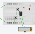
Experiment 9: Time and Capacitors asks you to construct the following circuit:


The purpose is to demonstrate that a capacitor can allow a signal to pass through it. By pressing switch A, the capacitor charges and briefly illuminates the LED. Once "fully" charged, the LED no longer illuminates regardless of pressing switch A. To reset the capacitor, pressing switch B discharges the capacitor and allows you to illuminate the LED again with switch A.

Now, my question is why is the 10k ohm resistor necessary? Shouldn't a simple short circuit discharge the capacitor?
I templated this in circuits.io and it doesn't work, which is expected. But why? If the resistor is necessary to safely discharge the capacitor, why must it be connected to the negative bus? Why does it not work to put the resistor in the short circuit with switch B?

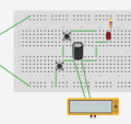
The following circuit illustrates what I'm imagining. After the capacitor has been charged, why doesn't pressing switch B create the short circuit path in yellow to discharge the capacitor?


If I had to guess, I suspect my confusion lies in a misunderstanding of the way capacitors work.

Thanks.
 

WBahn

Joined Mar 31, 2012
29,976
Now, my question is why is the 10k ohm resistor necessary? Shouldn't a simple short circuit discharge the capacitor?
It's not there to help discharge the capacitor, it is there so that there is a DC path to ground from the anode of the LED, which may or may not be there without it depending on the model used for the LED. Simulators don't like floating nodes and may not converge on an initial operating point when one exists.

I templated this in circuits.io and it doesn't work, which is expected.
Templated what? With or without the resistor? In what way did it not work? We aren't mind readers.
 

Thread Starter

Windburn

Joined May 20, 2017
7
Templated what? With or without the resistor? In what way did it not work? We aren't mind readers.
I templated it first as designed, and it worked correctly. Then I tried removing the 10k ohm resistor (1) and also placing it with in the yellow short circuit loop (2). In both iterations, the LED would light and fade when switch A was initially pressed, but switch B would not discharge the capacitor. I included a voltmeter in the template around the capacitor to observe the buildup of potential across the capacitor when switch A was pressed, but pressing switch B did not alter the measured voltage (in the simulator, of course).

DC path to ground
In a battery (9V DC) configuration, where is the ground?

keeps the node from floating
floating nodes
What are floating nodes and why do simulators not like them? Should I avoid them as a general rule?
 

MrAl

Joined Jun 17, 2014
11,389
Hi,

You did not really show where you connected the volt meters so there are some possibilities.

Another possibility is that you are measuring the left over stored charge in the LED, which has some equivalent capacitance across it's terminals. A voltmeter would tell you this or not.

Floating nodes are nodes that do not connect to anything. They are usually made when the terminal of a circuit element is left completely open in the schematic. However, there are other times when this can happen also.

For a resistor, one end open is not usually a problem because the solver looks for DC paths to ground and a resistor terminal always has a DC path to ground if at least one end of it is connected to another node that has a path to ground.
A capacitor on the other hand does not have a DC path to ground if ONLY one terminal does. Both terminals need a DC path to ground.
A diode anode may have a path to ground sometimes and not other times if only the cathode is grounded. That's because in the attempt to forward bias it fails it may start to look like an open circuit similar to a capacitor. This may vary with the type of simulator though.
Transformer secondaries may or may not look like an open circuit also depending on the model. A DC transformer model will not have this problem, but a coupled inductor model usually will.
When in doubt, connect a large value resistor from the node in question to ground. Normally a 10Meg resistor works, but it depends on the other circuit impedances also and if the internal solver is already near it's limit of precision.

The main reason floating nodes dont work well is because the algorithm does not know what it is connected to and does not want to assume anything, so it gives the operator a chance to correct a possible mistake. Remember the algorithm is a software device that must go through an interpretation stage in order to decipher the physical reality you are trying to convey with another non physical device: the software drawing. In theory you could create an algorithm that handles this, but today most simulators are not made to deal with it, they just reject it so that the operator has a chance to see if they made a mistake in the drawing which is a strong possibility if there is a floating node.
 
Last edited:

Thread Starter

Windburn

Joined May 20, 2017
7
You did not really show where you connected the volt meters so there are some possibilities.
I understand. Please see the following images for how I simulated the circuit.

As diagramed in the book:


Removed the 10k ohm resistor entirely:


Moved the 10k ohm resistor into the short circuit loop:


Again, thank you all for taking the time to help me learn.
 

Attachments

crutschow

Joined Mar 14, 2008
34,280
.........I included a voltmeter in the template around the capacitor to observe the buildup of potential across the capacitor when switch A was pressed, but pressing switch B did not alter the measured voltage (in the simulator, of course).
Was the voltmeter connected across the capacitor leads or from one lead to ground?
 

crutschow

Joined Mar 14, 2008
34,280
Below is the LTspice simulation of the circuit without the resistor to ground.
It simulates as expected.
The LED current pulses when S1 is closed.
The voltage across the capacitor, V(1,2), then goes to zero when switch S2 closes.
Since there is no resistor to establish the node voltage at 2 is floats at about 1.3V above ground due to the LED capacitance and forward bias voltage.

upload_2017-5-20_15-14-17.png
 
Last edited:

AlbertHall

Joined Jun 4, 2014
12,345
With your modified circuit, connect a 10k resistor in its original place (as well as your 10k in series with the switch).
If it is the floating node that your simulator doesn't like this modified circuit should work.
 

MrAl

Joined Jun 17, 2014
11,389
I understand. Please see the following images for how I simulated the circuit.

As diagramed in the book:


Removed the 10k ohm resistor entirely:


Moved the 10k ohm resistor into the short circuit loop:


Again, thank you all for taking the time to help me learn.

Hello again,

Ok that's good. Now what is the reading on the volt meter after 10 seconds with the shorting switch closed?
Also, can you connect another volt meter from the right side of the cap to ground, and if possible, a third volt meter from the left side of the cap to ground? And get the readings. So that would be 3 readings in total.
Also, what is the power source voltage? (another reading with another voltmeter if possible)
 

Thread Starter

Windburn

Joined May 20, 2017
7
With your modified circuit, connect a 10k resistor in its original place (as well as your 10k in series with the switch).
Yes, that worked. So it's the simulator I am using.

Also, what is the power source voltage?
9V DC

Ok that's good. Now what is the reading on the volt meter after 10 seconds with the shorting switch closed?
Also, can you connect another volt meter from the right side of the cap to ground, and if possible, a third volt meter from the left side of the cap to ground? And get the readings. So that would be 3 readings in total.
First, as diagramed:
After 10s A
Screen Shot 2017-05-21 at 1.02.01 PM.png
After 10s B
Screen Shot 2017-05-21 at 1.02.24 PM.png

Next, no 10k ohm resistor:
After 10s A
Screen Shot 2017-05-21 at 1.08.56 PM.png
After 10s B
Screen Shot 2017-05-21 at 1.08.40 PM.png

Finally, with the 10k ohm resistor in series with switch B
After 10s A
Screen Shot 2017-05-21 at 1.11.54 PM.png
After 10s B
Screen Shot 2017-05-21 at 1.12.14 PM.png

That last one is very interesting, because when that arrangement is tested without the additional voltmeters, the capacitor does not discharge. It's appears to be an example of the Observer Effect.
 

crutschow

Joined Mar 14, 2008
34,280
That last one is very interesting, because when that arrangement is tested without the additional voltmeters, the capacitor does not discharge. It's appears to be an example of the Observer Effect.
Because the voltmeter used for the observation has an input resistance that discharges the capacitor.
 

Thread Starter

Windburn

Joined May 20, 2017
7
Below is the LTspice simulation of the circuit without the resistor to ground.
Thank you. That is extremely helpful to see.

Would you mind expanding on this last sentence a little?
Since there is no resistor to establish the node voltage at 2 is floats at about 1.3V above ground due to the LED capacitance and forward bias voltage.
Finally, since it is diagramed in the book to include the resistor, even though it appears to not be necessary, could you speculate about why the author would include it? Is it safer? Are there "best practice" guidelines he is employing?
 
Top