Facebook
 Google
 GitHub
 Linkedin
Hi guys,
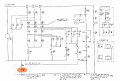
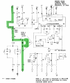
Quick question regarding a circuit containing a diode and capacitor in parallel with each other. In the schematic you can see that in one situation the DC takes the path from terminal 11 to terminal 3 as traced through the green highlight. The voltage is 125 VDC with positive at terminal 11. I'm just wondering what the purpose is of this configuration. Is the capacitor there to provide some extra "oomph" so to speak to the load (not pictured) downstream? If so, why is there not the same configuration on the outputs of terminals 1 & 2? Terminals 1, 2, and 3 all energize the same load individually at certain conditions, never concurrently. If it helps this is a circuit used in protective relaying for transmission lines. The eventual load is the trip coil for a circuit breaker.
Thanks,
Dave
Attachments
-
 678.8 KB Views: 131