Diode for contactors operation

Thread Starter

RefaelGalin

Joined Dec 31, 2017
9
Hello,

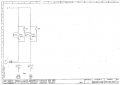
I am electrical engineer working in design and manufacturing of crane applications. For purpose of Hand/Auto switching we use two contactors operated at 400V AC. 1`st contactor A1 receive phase L1, 2`nd contactor A1 receive phase L2. A2 of both contactors receive phase from Hand/Auto switch which toggles between L1 and L2 phases. Problem arises when there is disconnection in toggled phase to A2 of contactors. Then contactor coils connected in series to 400V AC by phases L1 and L2. This causes contactors to shatter and burn eventually.
I want to implement diodes in series to contactor DC coils, so when toggled phase disconnects (failure or emergency) there will not be series connection between contactors coils.
Please advice in choosing right diodes and your thoughts on implementing this solution.
Thank`s in advance.
 

Attachments

dendad

Joined Feb 20, 2016
4,476
Sorry, I can't figure out your circuit symbols. It is probably standard switchboard symbols.
But you look to be using diodes on AC run coils. Is that so? If it is, you will be running half wave rectified pulses into the coils. Is L1 and L2 referring to AC Phases?
It is looking to me like 1-2 shorts 2 phases together.
I feel dumb ;)
 

Thread Starter

RefaelGalin

Joined Dec 31, 2017
9
Sorry, I can't figure out your circuit symbols. It is probably standard switchboard symbols.
K024, K026 - contactor coils, originaly coils are 400VAC. after adding diodes i will change contactors to dc coils for appropriate voltage.
S012 - toggle switch two position.

But you look to be using diodes on AC run coils. Is that so?
After adding diodes i will change coils to dc.
Is L1 and L2 referring to AC Phases?
Yes.
It is looking to me like 1-2 shorts 2 phases together.
It toggles between two states, L1 or L2.

Thanks
 

dendad

Joined Feb 20, 2016
4,476
Would not the problem go away if you have seperate wires from each half of the auto/manual switch to the appropriate KO24/KO26?
 

Thread Starter

RefaelGalin

Joined Dec 31, 2017
9
Would not the problem go away if you have seperate wires from each half of the auto/manual switch to the appropriate KO24/KO26?
Yes, but i have design constraints. The system is on moving platform supplied by busbars tens of meters long. Additional wire means additional busbar.
 
Last edited:

dendad

Joined Feb 20, 2016
4,476
A good way to get power diodes that will be easy to mount is to use a bridge rectifier as a big diode.
Just use the + and - connections and ignore the AC ones.


Or in this case, you could use just one bridge.....
Bridge2.jpg

And connect it like this..
auto-man-relays.jpg

Added capacitors across the contactor coils to help filter the pulsating DC may help the chatter if required. Try it first to see how it goes.
A 25Amp 800V bridge will be bullet proof.
https://au.mouser.com/productdetail/on-semiconductor-fairchild/gbpc2508?qs=sGAEpiMZZMtQ8nqTKtFS/LDhWhDI65ns7u9OdLOIdz0=

But if you like, go for a 1000V one.
https://au.mouser.com/productdetail/genesic-semiconductor/kbpc1510w?qs=sGAEpiMZZMsra/h506hF%2bLTR6GbaEEzqZjhP96IkF%2bc=
 
Last edited:

shortbus

Joined Sep 30, 2009
10,045
K024, K026 - contactor coils, originaly coils are 400VAC.
You don't say what part of the world you live in or where these cranes will be used. but for the most part control voltage is limited to ~120VAC or DC. So why are you using 400 volts on the controls?

Yes, but i have design constraints. The system is on moving platform supplied by busbars tens of meters long. Additional wire means additional busbar.
Any crane I've ever seen or used, has the bus bars only supplying the motor power. The control is done in a control panel and then sends it out to the buss bars. The contactor's normally used for cranes also have a mechanical interlock built into them. Too avoid the crane doing something it shouldn't. Any overhead lifting system needs to be very particular in what it does and when it does it, there are many regulations in place most places to make sure the crane is safe. That is why they designed special contactors just for cranes.

I may be wrong about your question, but it seems more like a "homework" assignment than one from someone that is building a real world crane and not knowing even the basics of its control.

https://www.craneproparts.com/crane-contactor.html
 

MaxHeadRoom

Joined Jul 18, 2013
28,688
Your schematics do not appear complete, for a simple manual/auto feature, I would think either existing interlock contacts or a small aux relay could be used, not the diodes.
Also what type of crane, Gantry? Jib? etc.
Max.
 

Thread Starter

RefaelGalin

Joined Dec 31, 2017
9
You don't say what part of the world you live in or where these cranes will be used. but for
the most part control voltage is limited to ~120VAC or DC. So why are you using 400 volts on the controls?
It is an automated storage retrieval system with two cranes and conveyors. Crane panel control voltage is 24 VDC for all the sensors, barcode reader and etc. Crane automated or manual operation is controlled from control box located at the entrance door to restricted storage area outside the cranes. The idea is to control automated or manual crane operation by singe additional busbar.
It is important to have separate contactor for hand mode and for automated mode operation.
Hope I clarified.
 

Thread Starter

RefaelGalin

Joined Dec 31, 2017
9
Your schematics do not appear complete, for a simple manual/auto feature, I would think either existing interlock contacts or a small aux relay could be used, not the diodes.
Also what type of crane, Gantry? Jib? etc.
Max.
It is warehouse storage and retrieval system crane. As i said at the thread there are some design constraints, in practice it is not simple as seems.
 

Thread Starter

RefaelGalin

Joined Dec 31, 2017
9
Your schematics do not appear complete, for a simple manual/auto feature, I would think either existing interlock contacts or a small aux relay could be used, not the diodes.
Also what type of crane, Gantry? Jib? etc.
Max.
We have experience with manual/auto switch based on two additional control busbars, as i said the idea is to reduce to one control busbar.
 

Thread Starter

RefaelGalin

Joined Dec 31, 2017
9
I am attaching schematic of exist hand / auto changeover made by german crane manufacturer.
P is toggled between L1 or L2 by remote switch.
Please elaborate for your understanding the purpose of : v1, v2, Y31 and the capacitor.
Thanks
 

Attachments

Top