Facebook
 Google
 GitHub
 Linkedin
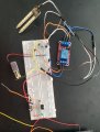
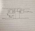
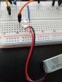
Hello, I am very new to circuits but have taken on a small project to learn more. Part of the circuit involves powering a small solenoid, after testing it a bit I found it works best between 7-9 Volts and my power supply is a tenergy 9v battery. My only issue is that from my understanding I need a diode to protect the rest of my circuit when the solenoid shuts off but the kind I have keep burning out at that voltage but if I add a resistor to protect it can't get the correct voltage to the solenoid. Are there any higher voltage capable diodes anyone can recommend or perhaps ways I can make these work. Apologies as I do not know the part number for said diodes but will include a picture.
Attachments
-
 1.7 MB Views: 15