Diode blinking?!?!

Thread Starter

Myronaz

Joined Jan 3, 2018
32
Hello,

The 4E and 6K could be production codes. It will have no influence on the actual function of the part.

Bertus
Oh I figured as much, but I wanted to check here to make sure so I don't screw up the rest of the circuit, thanks a bunch! I hope this is the problematic part, or maybe it just died by reverse polarity, I don't know, though wouldn't that mean it protected the rest of the circuit by dying? im not sure, whatever the case it's worth a shot since I have no other clues
 

Thread Starter

Myronaz

Joined Jan 3, 2018
32
I should also mention that when I got the phone, there is a chance that it was FINE, but the type of adapter it required was the longer barrel one, which is very rare, so I went around various shops in my city and tried to look for one, finally I came across that electrician and he told me he can get me one, he took a standard Philips DC adapter, chopped the power jack off and soldered in a new one that fitted the phone's socket, after that it still didn't turn on, then he checked some readings with some analogue equipment and he slightly freaked out and said in a rush tone 'Oh sorry it looks like it's broken, now I have to close the shop so please leave quickly' does that mean he screwed up polarity which resulted in that blinking diode? I also had someone check the adapter and he told me it was 19 volts, when the rated voltage for the phone was 9 volts, so maybe it was actually over voltage that killed it? or maybe both? Either way that little incident is a little too suspicious, wonder if the phone was already broken or if he was the cause, that I don't know

Before that incident I also found a matching type adapter that fitted but it was only 4 or 5 volts so maybe that's why it didn't turn on, although under voltage could of have killed it as well? Again i'm not sure, there are just too many things to consider so it's hard to draw a conclusion, but for now ill just replace the regulator and see what happens
 

Thread Starter

Myronaz

Joined Jan 3, 2018
32
Heyo,

Replacement regulator has arrived, but im facing a dillema with the polarity of the regulator

So...


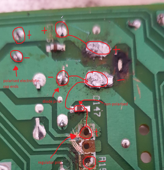
Taking a look at this image, we have already figured out that the negative power pad is the bottom pad, right? Well from what I can see, the positive pin of the transistor was connected to the bottom power pad, which is the negative one, so what? That's not supposed to be that way is it? Unless im misunderstanding how pinout for the regulator is

If the front side left pin is negative, then from this picture of the originally installed regulator, we can see that the regulator's front side is facing me, which means that the left pin (<) is negative, meaning that the positive pin is connected to the negative powerpad


So... what's going on here?!?! Am I missing something? Or am I misunderstanding the regulator? Surely the polarity of the power pads isn't wrong, because the big electrolytic polarised cap's negative side is directly connected to the bottom power pad

P.S. ignore the mess on the regulator side, the pads ripped out as soon as I removed the solder, so I scratched the surface of the tracks to make a connection through them, since there are no pads anymore
 
Top