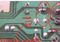
My guess is that the pin from the black-striped side of the big cap connect the the same large copper pour that your "diode" arrow head overlies as the diode. That would likely be the negative (cathode) end.
My guess is that the pin from the black-striped side of the big cap connect the the same large copper pour that your "diode" arrow head overlies as the diode. That would likely be the negative (cathode) end.
You might be able to short the capacitor and then watch the ohmmeter as the capacitor charges.
In many if not all circuits one of the first things that a power input connects to, after the power switch if its there, it a capacitor, and most likely an electrolytic capacitor. Trace by eye or with a low ohmmeter setting from the input to a terminal on an electrolytic capacitor near the input. That will tell you the likely correct polarity of the input.
You might be able to short the capacitor and then watch the ohmmeter as the capacitor charges.
In many if not all circuits one of the first things that a power input connects to, after the power switch if its there, it a capacitor, and most likely an electrolytic capacitor. Trace by eye or with a low ohmmeter setting from the input to a terminal on an electrolytic capacitor near the input. That will tell you the likely correct polarity of the input.
I can understand what you mean, I can get the meter to show other capacitors in the board slowly charging, but the big red cap doesn't show anything on the meter, and the blue one that is cinnected directly to the bottom power pad doesnt charge, the reading is stuck at 0.01 ohms, does that mean they have gone bad? maybe from me connecting the wrong polarity?
Also the black side of the blue cap (i think that means the negative side) is connected directly on the same track as the bottom power input pad, does that mean that pad is negative?
Heh...that's a first for me..
I haven't seen a diode do that and remain in one piece.
The "blink" in the diode looks like a spark. Are the battery connections correct? Were any parts changed? The spark seems to occur at a regular interval like its caused by an oscillation.
I see what you mean, when you said big cap i thought you meant the big red one which isnt really on that area so I got confused, but I think thats definately the negative pad, interestingly I tried reversing the polarity and no matter whether positive or negative is connected to the bottom pad, the diode blinks and there is no difference, since I connected positive to the bottom, could that of have killed of the capacitor? when I try to charge it with the ohm setting, it's stuck at 0.01 and doesnt increment at all
My thought is that the blinking diode is there to prevent having a power supply connected with the wrong polarity. With the foil exposed, make sure that the POSITIVE polarity of the power supply is connected to the same foil that has the black band of the blinking diode connected to it.. If you have been connecting the power supply the wrong way, toss the phone. The diode tried to do its job but died in the process, thus allowing reversed polarity to the rest of the circuit.
When you say you connected the pos or neg to the pad, do you mean pos or neg probe of your meter or the power supply? I would find it odd that your meter will supply enough current to make that diode flash. If you intentionally connected the supply with opposite polarity, you may have ruined other parts.
I have been referring to the polarized electrolytic capacitor, not the large (physical sized) non-polarized capacitor. Do you know what an electrolytic capacitor looks like?
When you say you connected the pos or neg to the pad, do you mean pos or neg probe of your meter or the power supply? I would find it odd that your meter will supply enough current to make that diode flash. If you intentionally connected the supply with opposite polarity, you may have ruined other parts.
I have been referring to the polarized electrolytic capacitor, not the large (physical sized) non-polarized capacitor. Do you know what an electrolytic capacitor looks like?
I sort of know what you mean when you say electrolytic capacitor, it's the blue ones in the board (I know sometimes shape and colour can vary) but in this case they are blue, anyways its not the multimeter that makes the diode flash, it's connecting the power supply that does, first time I tried it was with the correct polarity (negative on bottom pad and positive to top pad, the one closer to the edge of the board) and the diode started flashing, then I tried reversing the polarity, and it still blinks, I realize I may of have done more damage
Interestingly the actual phone part of the circuit works, it can make calls, receive calls so on and so forth, that part always did, even adter getting polarity wrong, the part that doesnt work is the cassette part, because it needs external power and obviously we are having problems with that
For now I want to try replacing the big red cap and the blue one that sits next to the power jack pads, as well as the diode, I can identify specifications for the caps, but what about the diode? How am I supposed to know that if I dont have a schematic
Capacitor failure in capacitors that aren't swollen is rare. If you want to test the capacitors with your ohmmeter function you will probably have to remove them from the board first.
Capacitor failure in capacitors that aren't swollen is rare. If you want to test the capacitors with your ohmmeter function you will probably have to remove them from the board first.
As a general rule, I frown on making more than one change at a time. If you make three changes, and it stops working, how do you know whether one change may have made it work and the other two made it stop working, etc. Lots of combinations to test.
I would not replace either capacitor, unless you have reason to suspect they are defective. They do not look defective, and non-polarized ones rarely fail. Replace only the diode. What diodes do you have available?
That will kill a tantalum -- often spectacularly -- your aluminum electrolytic, which is what it looks like, may have survived. The non-polarized one would probably survive.
As a general rule, I frown on making more than one change at a time. If you make three changes, and it stops working, how do you know whether one change may have made it work and the other two made it stop working, etc. Lots of combinations to test.
I would not replace either capacitor, unless you have reason to suspect they are defective. They do not look defective, and non-polarized ones rarely fail. Replace only the diode. What diodes do you have available?
Spectacular failure, maybe, but I've seen many capacitors fail by ESR increase without blowing up. They may still have rated capacity and appear perfectly normal, but have a resistance that has gone from <1Ω when new to >50Ω.
That is not a regular diode, It is a very special temperature stable reference diode. Save it for a future project.
If there are no numbers on the defective diode then you will have to guess. Start by trying to guess or figure out the voltage in the circuit. From the photo it might be something like a 1N914 and maybe good for 200 milliamps. Some times you guess wrong and the diode doesn't work in that circuit or is destroyed. That's sometimes part of the process.
That is not a regular diode, It is a very special temperature stable reference diode. Save it for a future project.
If there are no numbers on the defective diode then you will have to guess. Start by trying to guess or figure out the voltage in the circuit. From the photo it might be something like a 1N914 and maybe good for 200 milliamps. Some times you guess wrong and the diode doesn't work in that circuit or is destroyed. That's sometimes part of the process.
Then would something like this work? (click the highlighted 'this' word to follow the link)
Edit: fixed the link, for some reason the same picture of the diodes was in it, not sure why...... but its fixed now for anyone that may of have been confused

 Facebook
 Google
 GitHub
 Linkedin