My knee-jerk reaction to supplying two voltages for a test was that it would be a pain. But all I had to do was carry my DC power supply out to the garage and repeat my testing out there. Plugged the pump in normally and discovered there was 12V on that center pin already, whether the PS was supplying 3.3V or not. Can't be good.
So I cut the connections to the PCB and confirmed the pump runs just fine. Draws just under 2A with no load and over 3A with my thumb over the air exit hole. Maybe my grandson can use it in a robot competition or some other project. If I could figure out how to use that pressure sensor, I could still use the pump as intended, it just wouldn't be 'smart' anymore.
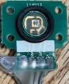
I couldn't help myself - I had to look inside that pressure transducer to see if there is a part in there that might have a data sheet. There is not. It appears to be a custom part. The black ring is part of the seal and the part you see inside that faces the pressure.
I'm guessing pins 1 and 4 are ground and power, leaving 2 and 3 for the output signal.
I'm kinda doing this same thing myself (at some point in the future - right now, it isn't a priority); after I saw a sale on one of those super-cheapo digital tire pressure gauges (I think I spent all of $3 on it) on Amazon - I bought it just for the sensor.
I'm basically wanting to build a pump for Lego pneumatics - because the regular pumps (Lego) are fairly expensive, and the analog pressure gauge made for the system is even more expensive.
So at first I thought - well, I could use one of those gauges, and maybe just hook it up to read the pressure. After I got it, and took it apart, it didn't look like I could easily repurpose it - but I could do something with the sensor. After I learned about the above boards and that they could be used to read the sensor...I then realized that "why build a Lego pump, when I could just buy one of those cheap lipo battery-powered air pumps".
I found one on sale for $10 and I think I can pull it apart and "repackage" it to use for Lego stuff. Worst case, I'll have to "rebuild it" - but it does have a similar gauge and such on it, plus "smarts" to shut off at a certain pressure (likely the same as yours) - hopefully I won't have to recreate all of that.
But if you wanted to - the trick is "calibrating the sensor". There's plenty of code out there on how to read the sensor, but unless you have an actual datasheet for your exact sensor, there is a certain "fudge factor" multiplier you have to apply to get an accurate reading. It can be computed - but you have to be able to take some measurements with known pressures.
For my purposes, I was just going to make a simple adapter, and some kind of "homemade tank" (a 2 liter bottle would work) - because I only needed a max of 30 psi. But if you wanted to go beyond that, one of those portable air tanks you can fill with a "real compressor" might be the better deal, if you can get it up around 50-75 psi. I'm not sure what those tanks max out at.
Then I was just going to use a tire gauge or something to set the pressure in the tank (while connected to the sensor), which would give me a reading (ie - 5 psi = <some decimal value>) - then I could use those values to get that "fudge factor".
What's crazy - I could never find one of those pressure sensors cheaply on Amazon - or anywhere. I wanted a sensor of around or above 200 kpa (which is almost 30 psi); the cheapest way to get them that I could find was to buy those tire pressure gauges and cut 'em loose.
The ones you can get as "modules" (for like an Arduino) only measure something up to 5 psi or such.
I found that the likely next best and cheapest pressure sensor (that also has data published) is a particular Bosch MAP sensor for turbo-charged engines. There are cheap 3rd party versions (around $10-15), you just have to cross-ref to the Bosch sensor in order to get the data for it (which has the proper equation to plug into your code to get an accurate reading). I managed to find everything I needed - plus the sensors are simple resistive output; you just put 5 volts to them and read the voltage, run it into an ADC and get you value, then apply the equation.
Even so - they still weren't cheaper than one of those cheap digital pressure gauges plus one of those amp boards. But it did seem like another viable option (a similar option is a fuel-pump pressure sensor, which is basically nearly identical to some of the MAP sensors).

 Facebook
 Google
 GitHub
 Linkedin