Digital Works 95 - 7 segment counter

Thread Starter

mibz7886

Joined May 21, 2020
9
I am struggling with my attempt with this problem
The Problem:
Design a circuit to take binary inputs and display a number on the counter. The counter needs to display the number 2 followed by 0 to indicate the current year the coursework was done (i.e., 2020). Then, this will be followed by your unique student ID number (person number). This means that everybody will have a unique problem to solve as no two students have the same student number. As an example, if your student number is 123456, your counter needs to display 20123456.

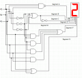
Build a circuit using only logic gates AND, OR, NOT, NAND, and NOR to simulate the counter. You should use 3 sequencers or bit generators in your circuit as input, and draw your circuit using Digital Works 95. The numbers should change automatically without any user intervention. (HINT: First construct a separate circuit for each segment from the truth table you have constructed. Then redraw the circuit to combine the separate circuits to form one complete circuit.)

Each of the wires on the counter below corresponds to a segment in the counter. If the wires on the counter are labeled a to g from left to right, the wires relate to the segments as follows:

Provide a brief description of how you will modify your circuit to display the number sequence in binary, using an 8-bit binary number representation for each number. Try and think about how you will make the modifications using as few gates as possible. (NOTE: only a brief textual description is required, you do not need to draw the actual logic circuit.)


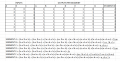
I have first constructed a truth table for each segment of the counter. I then derived and simplified each expression for each segment and then attempted to construct the circuit according to the expression of each segment. However, once I made the circuit I was trying to produce the first number by putting all the possible inputs into each sequencer and sort of messed around with the combinations of inputs until I got the first number which is 2. I could not achieve to display the number 2 which led me to believe there is something wrong with my logic. I am not looking for anyone to solve the problem for me but asking for guidance and advice as I am a beginner at this and struggling to understand.
 

Attachments

dl324

Joined Mar 30, 2015
16,839
Welcome to AAC!

Could you show your Kmaps and write the expressions without the 'x' (e.g. instead of !ax!bx!c, write A#B#C#).

You should be consistent. If you're going to label the inputs in the table with capitalized letters, you should use capitalized letters in the boolean expressions. You used caps for the inputs and the outputs; that can be confusing. Note how lowercase letters are used to identify the segments in the display. You should follow that convention.

clipimage.jpg
Why did you choose to use a different input for the 3's and 8's. I would have done it differently. Read the 4th paragraph of the instructions to see if that will change your implementation strategy.

Ignore the previous paragraph; you're limited to 3 sequencers, so you can't do the obvious thing.
 
Last edited:

dl324

Joined Mar 30, 2015
16,839
Here's what your table would look like if you reduced column widths (you don't need to leave them the default width):
clipimage.jpg
This makes it easier to see suspicious looking entries. Why do you have two values decoding 8 and 3? You have 6 unique numbers, so some rows could be don't cares.
 

dl324

Joined Mar 30, 2015
16,839
I see that you're checking this thread. Do you have anything to say?

I don't know why they're teaching students to use A as the MSB. If you use datasheets from the 70's as an example, A is always the LSB. This is from a National Semiconductor datasheet:
clipimage.jpg
clipimage.jpg

I checked your boolean expressions for the segments and you have at least one error.

What is the count order you defined in the sequencers? Whether or not your circuit will work depends on that.
 
Last edited:

Thread Starter

mibz7886

Joined May 21, 2020
9
My apologies for not responding. I have to decode the values 8 and 3 twice because that is just how my student ID is. I have changed the capital letters in my table to be more consistent in my expressions. I am struggling to define a count order for my sequencer as I have no implementation strategy for this. As I said I am a beginner and I don't have all the knowledge disposable
I have attached my first attempt at my circuit. I know it is messy but bear in mind that this is just my draft. There are no values in the sequencer and implemented each segment according to my expressions.
I will go back and check over my expressions as well.
Thank you
 

Attachments

dl324

Joined Mar 30, 2015
16,839
I have to decode the values 8 and 3 twice because that is just how my student ID is.
Think about this more. Your ID has 6 unique numbers. The sequencers can count in any sequence you desire.

What would you do if all digits were the same?
I have attached my first attempt at my circuit.
Please attach your .dwm file. You may have to change the extension to something allowed; e.g. .txt.
 

dl324

Joined Mar 30, 2015
16,839
I know it is messy but bear in mind that this is just my draft.
There is no excuse for your work to be messy. I solved this problem (both parts), and I solved the first part two different ways (my way and yours, although there are many solutions; some just make more sense than others). Neither of my logic diagrams had unnecessary wire jogs, non orthogonal wires, or wires crossing over components. I give you credit for labeling the sequencers.

I made an attempt to align gates and I labeled them; both for myself and whoever had to read them. When I wired things, I made a couple of mistakes (connected to the wrong polarity of a signal), having labels made it easy to find and correct.

I don't think I should show you an example because, if I was your teacher, I'd be grading on neatness.

I thought I'd try to see if you implemented the boolean expressions you derived in your first post correctly. The first thing I noticed is that you say segments 'a' and 'd' are TRUE, but you wired them as AB.

I'll give you this. You're using 5 inverters, but you only need 3.

When I want to post output from Digital Works, I print to PDF and take a snapshot from that:
clipimage.jpg
As you know, or will learn, Digital Works will treat any unconnected inputs as logic LOW. It's not a good practice, but I take advantage of it to avoid clutter and some work.

I made a compromise and routed wires over the text for the LEDs because they were only used for debugging. Also note that I ran the wire for the MSB over the pins for the 4th digit (which was unused). I could have moved the display up a grid, but you know how crude the move and wiring capability is. It just wasn't worth the effort. I just wanted to test that my BCD to BIN converter was working correctly.

EDIT:
I just tried DW version 2.04. I forgot how crude it was compared to 3.0.5.0.
 
Last edited:

Thread Starter

mibz7886

Joined May 21, 2020
9
Think about this more. Your ID has 6 unique numbers. The sequencers can count in any sequence you desire.

What would you do if all digits were the same?
I would try to produce the first number and then copy the inputs for the rest of the count across the 3 sequencers.
 

Thread Starter

mibz7886

Joined May 21, 2020
9
Also thank you for the criticism I will work on the neatness of my circuit. I was confused about how to wire segment A as I do not know how to wire for a True value as once again I am still learning
 

dl324

Joined Mar 30, 2015
16,839
thank you for the criticism I will work on the neatness of my circuit.
Many would object to constructive criticism. Your willingness to use it as a way to improve speaks well for you.
I was confused about how to wire segment A as I do not know how to wire for a True value as once again I am still learning
What logic level do you associate with TRUE?

You can use one of these supplies for fixed logic levels:
clipimage.jpg
 

Thread Starter

mibz7886

Joined May 21, 2020
9
The only logic gate I can think of is a 3 input OR gate or a NAND gate however I know this is incorrect because all outputs are not all true for both but to my knowledge these gates are the closest I can get to all true output for all possible inputs by using a gate. I associate TRUE with 1. I can only use AND, OR, NOT, NAND, and NOR to simulate the counter. I am not allowed to use a fixed logic level. I have produced the first number with only 0 in all 3 sequencers.
 

Attachments

dl324

Joined Mar 30, 2015
16,839
I am not allowed to use a fixed logic level.
I'd seek clarification on this from your instructor. Maybe they didn't comprehend the fact that some segments might always be on or off.
I have produced the first number with only 0 in all 3 sequencers.
This schematic looks better. You still need to work on unnecessary wire bends.

Your instructor gave a hint that you should work on the logic for segments one at a time and then combine them. I think doing them all at the same time saves time and is less tedious.

Did you use Kmaps to derive your boolean expressions? If you didn't, you should. I find them much easier to use than simplifying boolean expressions using identities that I don't remember any more.

What is it that you don't understand about sequencers?
 

Thread Starter

mibz7886

Joined May 21, 2020
9
Thank you. I will ask my instructor if I am allowed to use a fixed logic level. I will attempt to drive one segment at a time and no I did not use kmaps. I just used the boolean identities to simplify. I understand how to use the sequencers but I just get confused about the inputs needed when the whole circuit has been constructed. For example, I'm trying to achieve the 2nd number which is 0 but it cannot be produced. I have tried inputting all possible inputs for the 2nd count in each sequencer. However, i will try to drive one segment at a time for all 8 counts.
 

dl324

Joined Mar 30, 2015
16,839
no I did not use kmaps
You should use kmaps. They make it easier to troubleshoot any mistakes you make in your table or in your simplification.
I understand how to use the sequencers but I just get confused about the inputs needed when the whole circuit has been constructed. For example, I'm trying to achieve the 2nd number which is 0 but it cannot be produced. I have tried inputting all possible inputs for the 2nd count in each sequencer.
clipimage.jpg
From this I take it that the number you want to display is 20893385. To display 2, you're decoding a count of 0. What count do you need to decode to display 0? If you've tried all possible combinations for the second count, you have a problem in your logic.

If you attach your .dwm (change the extension to .txt), I can help you troubleshoot.
 

dl324

Joined Mar 30, 2015
16,839
I forgot to mention that all of your segment expressions were correct. The one I thought was wrong was a transcription error.

Regarding all of the work you did simplifying the expressions for segments 'a' and 'd'. Examine your truth table to see why that was unnecessary. Even when I used don't cares for some counts, I could see that 'a' and 'd' were "special".
 

dl324

Joined Mar 30, 2015
16,839
Thank you for your help. Progress is being made.
You should talk to your instructor about moving to Digital Works 3.0.5.0. You can download it here.

The newer version will show the logic level of all wires when you're simulating (and when you stop/pause them). That makes it much easier to troubleshoot. There's even a logic probe tool that's redundant and the version you're using would benefit from.

The V3 version can read V2 .dwm files, but not vice versa.

If you instructor won't upgrade, you can do your work in V3 and then re-enter in V2 to turn in.
 

dl324

Joined Mar 30, 2015
16,839
I didn't know that. Thank you. It will save me so much time troubleshooting
I forgot how primitive V2 was.

If you're having trouble with your circuit, post your .dwm file and I can show you how to use V3 to debug.

You'll have to redraw in V2 because that version can't load a file created with V3. V3 can read a V2 file.
 
Top